Hello, I am experimenting a similar problem that seen in this topic
,but let me develope a little bit.
The situation is that I am refurbishing a K40 generic laser with safety switches, analog panel, lights, the usual stuff you should do when you buy one of these ( The laser was working when arrived). The LSPS was upgraded with a new RS507, 700V, 5A bridge rectifier according to the info found here
Everytime I try to fire it there is a spark precisely between the HV and the HV electrode, no current measurement detected on the analog meter. I have redone several times the joint but there is always a “bang”. I really refuse to believe that the PS has gone bad, LEDs are lit and voltage is detected between terminal ( motors move accordingly).
Does anyone have a suggestion about this matter?
-The tube has never been used to engrave besides the firing tests ( no arcs or unusual sounds heard, just the regular sound of the HVPS) before the mod.
-I think the tube is from late 2015.
It was carefully disasembled from the supports and kept away while the modifications took place.
The optics wore protective hoods during the procedure.
The tube is always filled with distilled water + a few ml of PlantaMin (Tetra) when testing
And yes, arcing started after the mod. I will try to get a video.
Thanks in advance.
The mod was just to swap the bridge rectifier for a RS507, 700V, 5A bridge rectifier.
Well after some rework I can say that I have good news and bad news.
The bad news are that there is no video of the arcing.
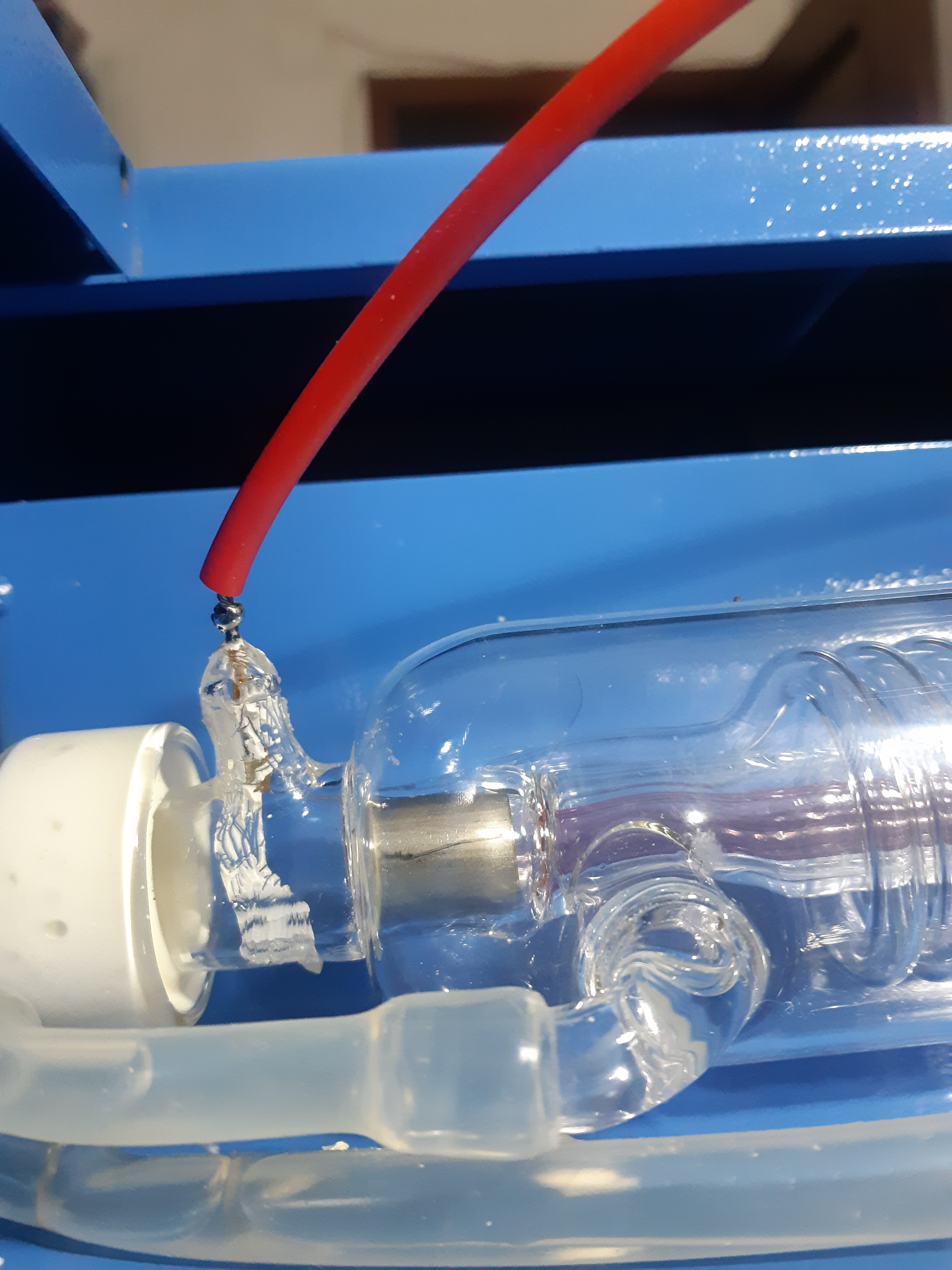
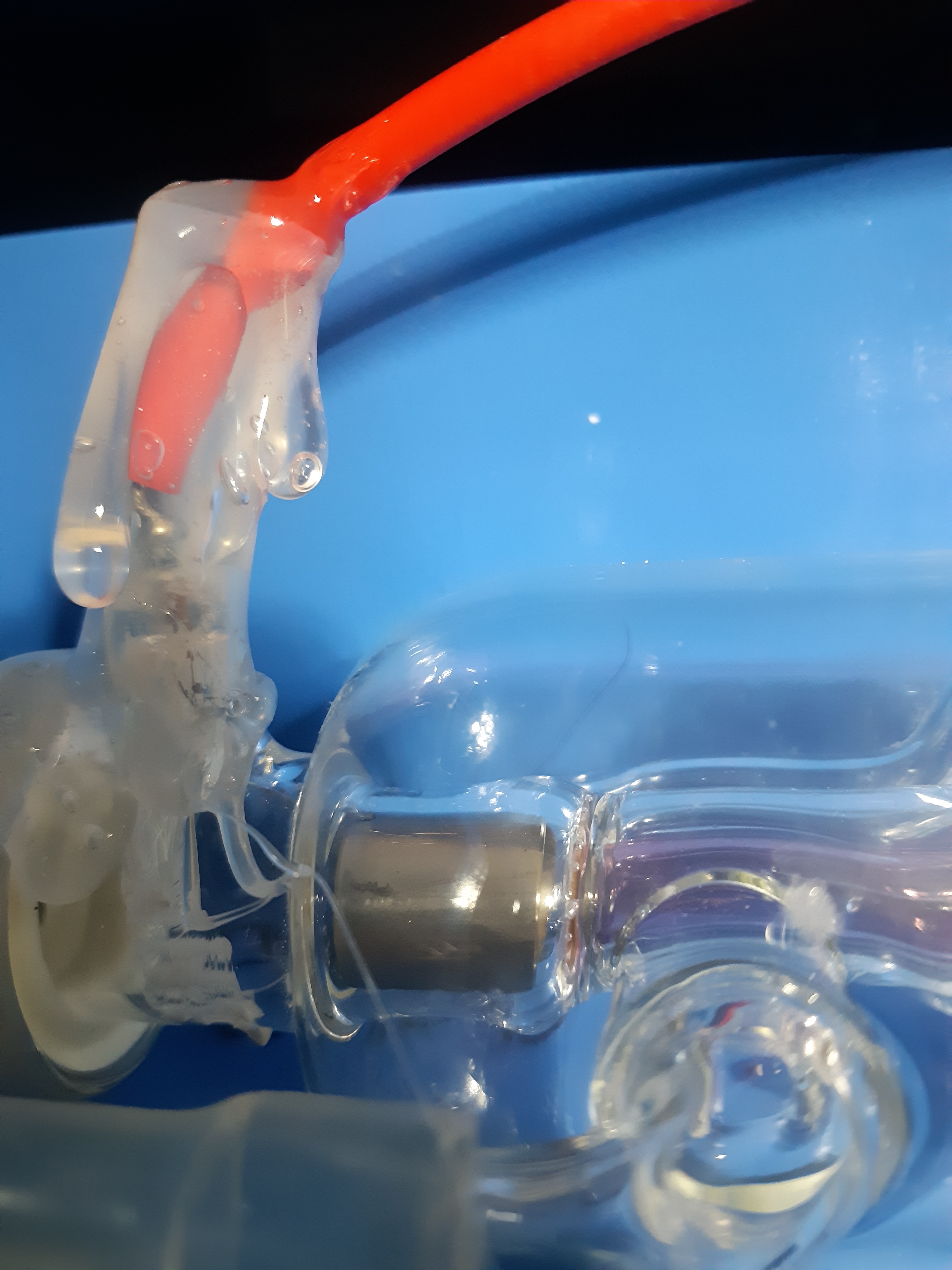
The good news are that there is no video because there is no arcing at all, the PSU just doesn´t make any sound at all but power LED lits. Below some pics :
The HV wire wraped around the Anode and soldered
Now I have several options, from buying a new one (but where is the fun in that?) to the non recomandable testing of the circuit. I´m inclined for the testing since I really need to know what could possibly go wrong here.
There really isn’t much you can easily test in this thing.
The driver circuits are just as unsafe as the HVT output, 600v at a lethal current.
To make matters worse the 600V is floating so it’s easy to blow up test equipment or electrocute yourself from the floating grounds. You have to have meters and scopes sitting 600v above ground if you mess with the output drivers.
First I would make sure that the problem is not external to the LPS.
Put it back in and determine if it will fire with the test button down on the supply.
Also, verify if the 24 and 5V are present.
If it fires then your problem is not the LPS.
If 24V and 5v are alive that is a good sign.
If not then it is likely the supply.
The lions share of LPS failures with no output are due to : #1 Bad HVT … most of the time
I am pretty sure the HV diodes in the HVT fail or the windings arc over.
#2 Fuse + rectifiers and or diodes but not that often
Then again it’s hard to say since you made mods at the components level.
I have tried to repair these supplies and it just not worth it.
If you replace the HVT and it fixes it you saved a few bucks.
If not it would have been cheaper to buy a new one.
Repairing one at the component level is arduous because most of the time if its not the HVT there are multiple component failures. When this supply dies there is so much energy involved it kills lots of parts and its certainly not a simple circuit to troubleshoot.
Probably you have the 24V and the 5V.
Only the high voltage side is not working.
If there is no smell of smoke probably the swtching FET-s are OK. Presume you soldered the bridge rectifier in the right direction.
More than likely the High voltage transformer. Probaly you hear the sparks jumps in side the transformer when you press the fire button.
Transformer is hard to test. What happening them is, the isolation is braking down. And the spark jumps inside. To do a proper test you have to build a test circuit. Testingit with 9V battery wont show if it is braking down at example 10.000V
But it is cheaper to buy a new power supply. You do not want to risk your new high voltage transformer anyway. And not at last you do not risk your life.
I was comparing the quality factors on the HV transformers.
The faulty one had about 35 while the good one had 130. on 10KHz.
That would be nice to see if that can be used as determine a faulty transformer.
And my test button on the power supply was even not connected. There is no trace going for the optocoupler.No surprise it did not fire for the test button. I think the maker deliberately was disconnecting the momentary test button on the power supply.
And it was arcing from the front panel. But probably the voltage was not high enough.
Well, after three ethernal months of waiting my new power supply arrived. I quickly wired up everything and pressed the test button just to find a low hissing…So now I have two HVPS and a nonworking laser.
Given the situation I decide to test the old HVPS, wired everything and leave 5 cm separation between the HV and return wires. When the test button was pressed a soundful spark appeared.
This makes me think that what is wrong with the engraver is the tube. The tube has been stored and unused for a few years, is it possilbe to have loss some of the gas mixture and so increase its internal impedance??? It would reaaaaaaally piss me off if now I have to buy a new tube.

 .
.