Hello!
Why in OpenRC Truggy drive shafts from front differential to axles are not parallel to the differential axis (in top view) and not parallel to the wishbones (in front view)? It makes turn angle in axle joints too big when the wheel turning inwards and the wishbone is in down position. I am trying to build joints myself, and in this position the joint’s ball falls out of the joint’s case.
Also turnbuckles are slightly not parallel to wishbones when moving up-down. Is it something important for car handling or what? It makes drive shafts go in and out from joints when all things moving.
I’m not 100% sure what you are asking in the 1st paragraph, I think something may be lost in translation for me. Can you clarify? Or maybe someone versed in RC cars knows what is being asked.
However, in your second paragraph, you asked/said: “turnbuckles are slightly not parallel to wishbones when moving up-down. Is it something important for car handling or what? It makes drive shafts go in and out from joints when all things moving.”
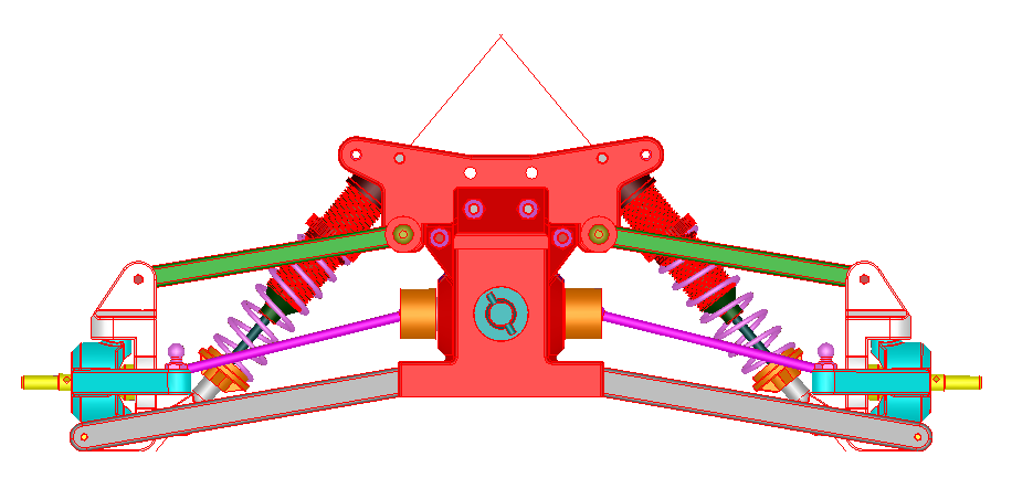
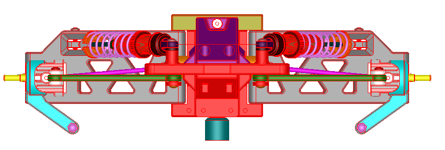
I think what you mean is that in the front view, the drive shafts coming out of the front diff and into the front wheels are not parallel with the turnbuckle or wishbone (which look to be parallel).
This is a good point (if I understand correctly). There’s a 4 bar mechanism between the frame, the turnbuckle, the wheel and the wishbone. If special care isn’t taken in the kinematics of the mechanism, the drive shaft is likely to get forced in and out during up and down motion of the wheel. Eyeballing the front view, it seems like this would happen.
Maybe someone will mod and post their improved version?
I wrote that differential rotational axis is slightly moved forward related to axis of the front wheels when they are directed straight forward. It makes:
- drive shafts (i am not sure about the name of the part. pink on pictures) are always tilted, even if the car is moving forward, with any load on shocks/springs. I think it stresses all joints more than if drive shafts were parallel to differential axis
- turning angle of the steering blocks are not symmetrical relative to drive shaft. It makes in one steering block to turn more than 45 degrees (relative to the drive shaft) in the end position, when another steering block turns less than 45 degrees at the same time. It gives even more stress to axle joint and takes some excess power.
- in unloaded state (wishbones are down, springs are relaxed) and when front wheel is turned inwards (for example right wheel is turned left), it makes maximum angle between drive shaft and wheel axle. In this position the ball of my drive shaft (dogbone?) is trying to leave it’s cup on wheel shaft(axle).
I am not sure it is design flaw. Maybe it is designed to be not parallel intentionally and it has some special purpose. I just want to know it, and is it worth it to re-design all the parts to be always parallel in all positions.
+André Roy, I think that @0667e468dbd4ad949aad is asking why aren’t the drive shafts parallel to the suspension arms, and centered on the wheels, when that makes bump steer and Ackerman angle problems? I’ve haven’t printed/built the truggy yet, but I know have the same question.
+André Roy, I think that @0667e468dbd4ad949aad is asking why aren’t the drive shafts parallel to the suspension arms, and centered on the wheels, when that makes bump steer and Ackerman angle problems? I’ve haven’t printed/built the truggy yet, but I know have the same question.
My thoughts are that if this is problematic, someone should work on a modification. :). Not having taken that close a look at the truggy, or how parts fit, I can see how the misalignment would cause undue stresses.
There´s always something that´s not going to be perfect i´m afraid. I fixed more problems on the Truggy than i can count along the way but unfortaunately that´s not one of them. Sorry!
It’s always good to shine light on these things. Ideally someone in the community besides yourself will take it upon themselves to improve this aspect of the design for everyone else.  They’d get attribution for their contribution!
@Daniel_Noree You shouldn’t feel responsible for fixing everything. I think that there was a feeling that it was intentional (suspension design is a bit of an art), and if that was the case, then he was asking about the rationale behind it. If it’s a bug, so to speak, then it needs to be logged and it’s the community’s responsibility to fix. That’s how open source works. It shouldn’t all fall on your shoulders.
Ok, If this geometry feature is not something important, then I’ll try to re-design my truggy. I am doing it anyway, because I have bearings of different size (it’s difficult to get right bearings here, I use what I can get)
@0667e468dbd4ad949aad What do you think about just changing the geometry of the “C-Hubs”, moving the part of the outer part of the axle up a bit until it become parallel?
(Btw, sorry for my previous non-constructive answer. I thank you very much for your input, it´s very valuable!)
I can’t tell if it would help, I think “C-Hub” part is too small to bring much difference to geometry. I thought about re-designing wishbone or even move differential housing a little backwards. Anyways, it will be re-designing of several parts, not only one part.
Now I have paused making my truggy, waiting for bearings to come from China… I tried to build differential with 8x16x5 bearings instead of 10x15x4, but 8mm diameter axle shafts are too fragile.
Ok, keep us posted on your progress.