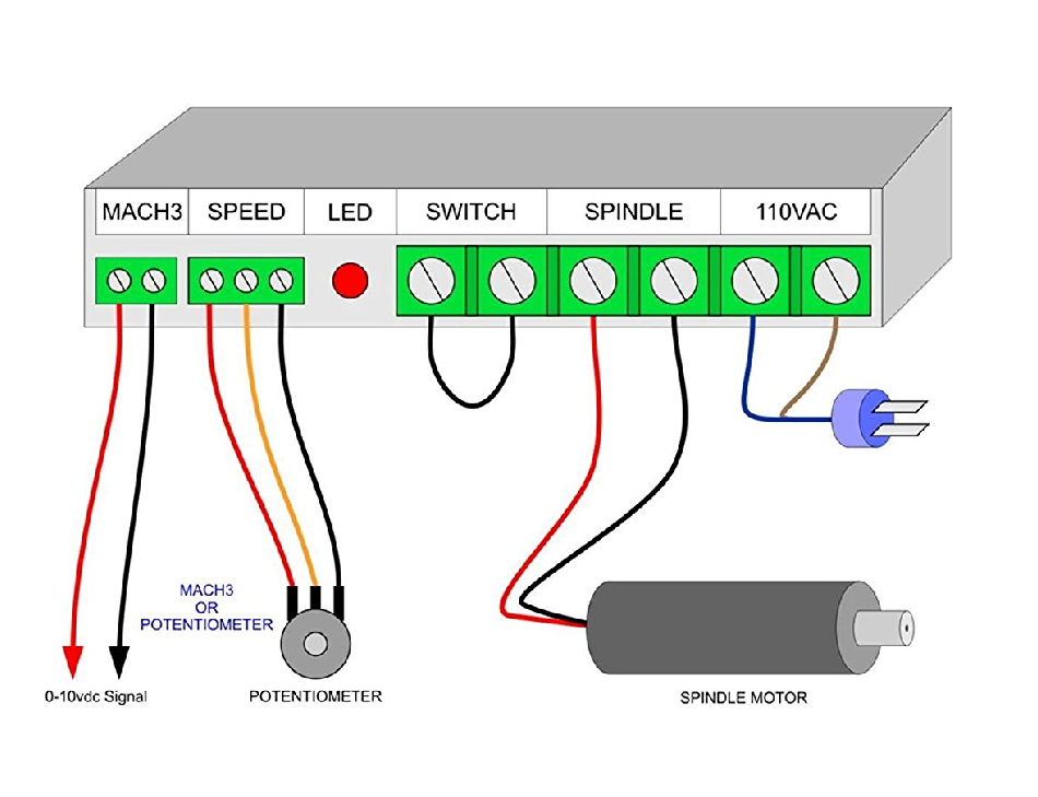
Hello all, I am in process of building a cnc router and could use a little help with the spindle module setup. I bought a cheap spindle and power supply from Amazon. The image says for use with mach3 via 2 pins on the supply (No data sheet though). I went to read the smoothie spindle pages and I think I just confused myself even more. Based on the attached image, can anyone help point me in the right direction to set up the spindle to be controlled by smoothie? I think I am going the pwm to analog route??
@Chuck_Comito can you point me to the setup you bought?
You can use a PWM to analog 0-10V converter running from the same port we have our K40 connected to.
Hello @donkjr , this is the spindle: https://www.amazon.com/dp/B01LNBOCDA?ref=yo_pop_ma_swf. I also ended up buying this today: https://www.amazon.com/dp/B06XB6J4FV/ref=cm_sw_r_em_apa_TFAVAb2GZEZDV
And yes the idea was to do exactly that using the same laser port pin. I pretty much thought I had this build in the bag until I saw the power supply for the spindle.
I just ordered the same unit from Amazon, so I am interested in what you learn as well. I will also be controlling with a smoothie board.
I will be sure to post back @Gary_Hangsleben . Don has helped me many times and I’m sure he’ll have some insights as well.
You can use a PWM to 0-10V converter like that: https://de.aliexpress.com/item/1PCS-PWM-to-Voltage-Module-0-100-PWM-Converted-to-0-10V-Voltage/32799217899.html?isOrigTitle=true
I would additionaly connect a “spindle enable” mosfet output to the switch input of the spindle power supply.
@cprezzi I think that is the same converter that @Chuck_Comito purchased from amazon above.
Does the smoothieware turn off the PWM when a motor start Mcode is not active? If so is a motor enable needed?
@cprezzi so I can better understand… the converter will change speed but not turn the spindle on and off so I would need to use the mosfet to do that function?
@Chuck_Comito
I suggest testing your PWM-> Spindle speed controls linearity. This would include the (Smoothies PWM)+ (PWM to Analog) +(Spindle Driver).
I learned the following:
… All the drivers that I tested (purchased online) and the one I am using have very poor speed control linearity.
… The linearity is caused by the motor drive erroneously turning back on during the end of the PWM cycle.
… Using a rpm meter you can map the actual speed vs programmed speed curve and then fudge it in the Gcode. This seems to be what most are doing. Some have firmware that makes this adjustment in software. For me this is a design defect and needs an improvement.
… Since speed setting is important in a router/mill for proper cutting, surface finish and tool cooling I decided to design a spindle driver that was more linear (I hope).
Your driver may behave better, I have not tested that model and would be interested in your results.
I am using my RioRand driver on my OX, meanwhile testing the new design.
Background:
https://plus.google.com/+DonKleinschnitz/posts/AG6gZ7Lxhs7
https://plus.google.com/+DonKleinschnitz/posts/jX6ZjgK9tgi
https://plus.google.com/+DonKleinschnitz/posts/M9xbk1JXryM

@Chuck_Comito for another purpose I tested this PWM to analog converter and found it had decent linearity.
@Chuck_Comito on my ox I do not have a spindle enable since the TinyG turns off the PWM with a M05 command and on with M03-M04.
I did add a switch in the 48V supply to the motor driver. When I screw up the Gcode and end up somewhere I shouldn’t be I can shut down the “pointy end” to minimize damage :). I have used this switch a lot :(. Its kind of a Estop for the spindle.
I’ve been reading your posts @donkjr , very interesting results. I’m not sure if this gets me anywhere though lol. I’m learing though! I saw you mentioned that you need a PCB layout guy from time to time. I’m very good at this. Let me know if you’d like something done. In the meantime, I’m trying to understand this whole thing. I think I’ve got my head around it but as I can see it is not as straight forward as I had hoped. I might be doing the spindle on/off and speed manually for a while…
First: I may later take you up on the PCB layout offer. I can hack together a board but its not a core skill. I plan to build one speed controller for myself and was willing to open source the design if someone wanted to make them for others. My current design is through hole and can be made much smaller with SMT, which I do not plan to undertake.
My speed controller will interface with 5V and 3V PWM signals directly without 0-10V analog conversion.
Second: Attached is a sketch of what I think you are trying to do. I looked at the parts you have chosen and think you will have some challenges with the interfaces because, as usual, they are poorly specified. This is why I trace these designs before using them.
The KNACRO pwm to analog suggests its needs a positive PWM of 0-5v but the input circuit is unknown, looks like an opto-coupler. My drawing shows a pull-up on the current common drain configuration from the smoothie. That approach needs a 5v supply which may be inconvenient. This module also requires 12VDC to run. Depending on the actual connection to the input no pull-up may be necessary.
The spindle controller wants a 0-10V signal but it is unclear what the output of the PWM-Analog converter looks like. I found one reference that suggested it was a LM393 with a 2200 ohm pull-up. There could be a mismatch to the spindle driver but only testing will tell. Its unclear how the pot works if the PWM input is used?
Of course you will have to config the smoothie with the correct PWM polarity and frequency.
Tracing the input and output of these devices will help bring clarity to the interconnections and may help to simplify the supply voltages and interconnects.
Some hints on wiring:
…do not run your motor drive wiring in or near a harness that has any digital signals like end stops :)!
… Run all low voltage signals like PWM and end-stops through twisted pair or shielded wire.
As always let me know if I can help.
missing/deleted image from Google+
@Chuck_Comito The spindle driver in your picture has a switch input (that is short out). This can be used to switch the spindle on/off either by a manual switch oder by a mosfet from the smoothieboard.
When you use mosfet you can safely enable (M3/M4) or disable (M5) the spindle with gcode. This way you reduce the risk of false signals (spikes, ground differences) on the PWM line that could start the spindle when it shouldn’t.
@donkjr You could use the psu of the smoothieboard to drive the 0-10V converter. And instead of the manual spindle on/off switch, I would use a mosfet output of the smoothie board. They are open drain mosfets, so they connect the output to ground when enabled.
For security reason, I would connect a mechanical switch in the 110V line to the spindle driver (just in case the electronics for on/off has a bug).
This way you reduce the risk of false signals (spikes, ground differences) on the PWM line that could start the spindle when it shouldn’t.… see your point, I never had this noise problem. Then again my PWM is open collector, opto isolated and shielded. If your PWM is not clean then it will cause other problems when running anyway.
You could use the psu of the smoothieboard to drive the 0-10V converter. Yes, that’s a good idea.
And instead of the manual spindle on/off switch, I would use a mosfet output of the smoothie board. They are open drain mosfets, so they connect the output to ground when enabled. I use the switch because I find that by the time I get to the console to turn off the motor from an Mcode the damage is done. I put the switch in the DC power output because switching the AC input still leaves the 48v caps to discharge before all the energy is gone and the motor stops. The switch is on a panel directly in front of me.
missing/deleted image from Google+
@cprezzi , I thought this was the case but doesn’t switching on the mosfet also apply whatever voltage I have on it?
@Chuck_Comito The open drain mosfets are like a switch in the ground line of the load. The plus pin of the mosfet connector on the smoothieboard is directly connected with the corresponding power input, but you don’t need it.
You just need to connect the gnd pin of the spindle driver with the gnd of the smoothieboard and the positive pin of the switch input with the mosfet out (negative pin) of the smoothieboard.
If you don’t know which is the positive pin of the switch input, it’s the one which has a voltage (against gnd) when the spindle switch is off (or short removed in your scematics).