helical infill d187|18
After i read the article
https://phys.org/news/2018-06-creature-feature-impart-superhero-toughness.html (via @rasha_kamel Thank you!), i thought this is easy to try, as Cura already has an option for line directions (top/bottom and infill).
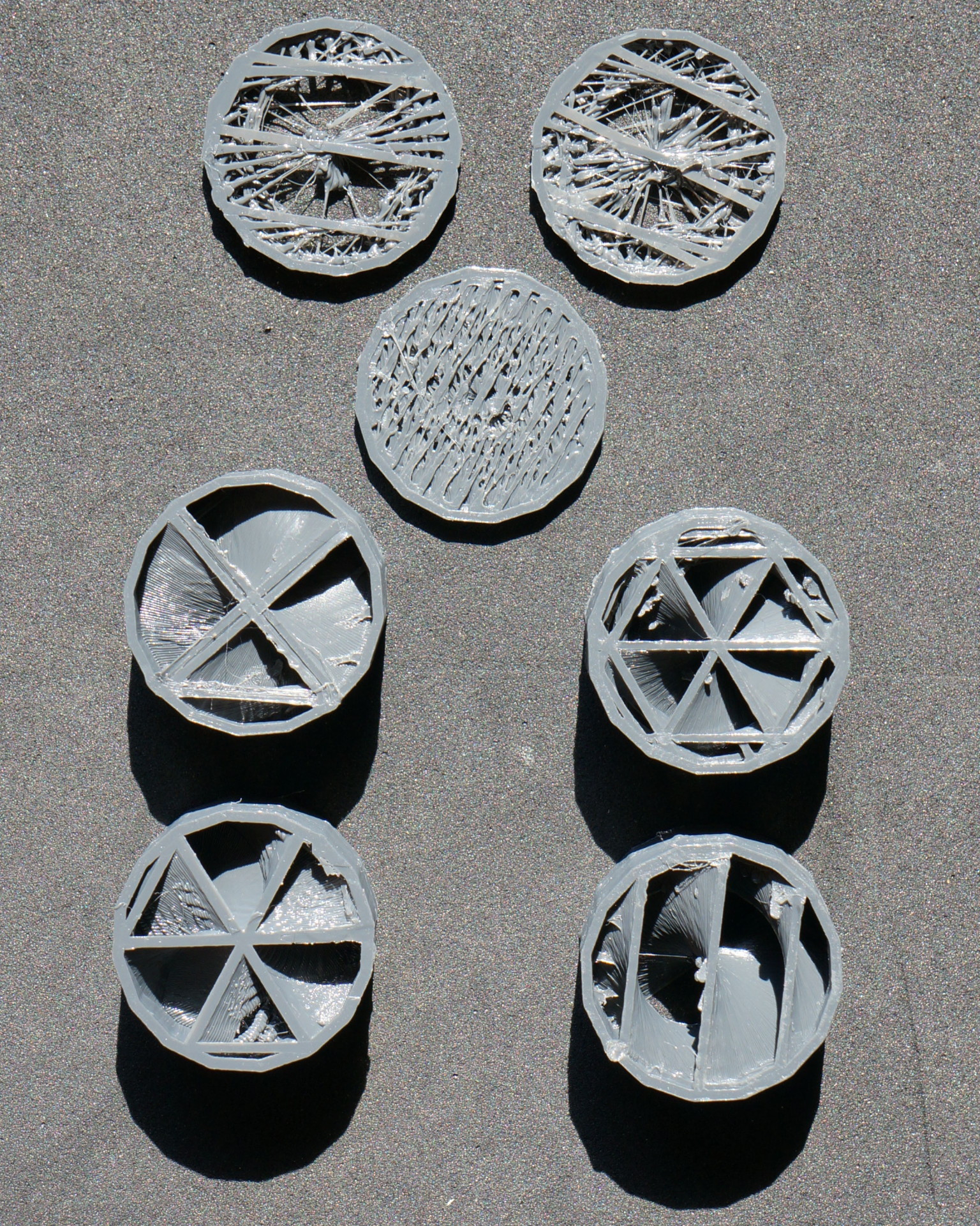
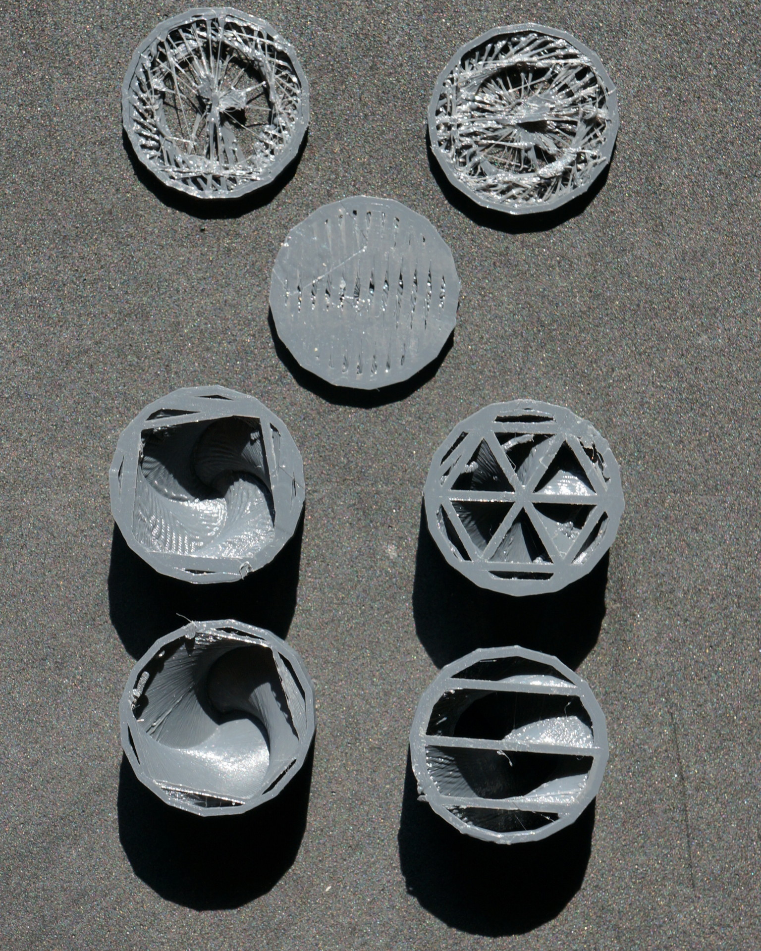
Normaly this is empty using 45°/135° (Δ 90°) but you can put in your own list. So the upper two disks have Δ 10° while the other using Δ1° (1°-180° while triangle need 1°-120°) hence resulting in a helical pattern.
Pattern of the four test cylinder are Octet, Triangle and second row Cube and Zigzag.
more stress resistance and preventing catastrophic failure at least that is how the bionic model predicts. You also didn’t use more material but get a more uniform stress distribution.
i assume, you have tried to create your own infill Patterns and failed?
Or what is the reason you posting it here?
Do you whant to present an project, an conclusion or want help ?
i can’t deduce your reasoning from your Initial post.
@Christian_Schulz I want to show you how you can use this technique to improve your prints. (this is posted in “Development/Hacks/Experiments” not help) Have you read the article https://www.sciencedirect.com/science/article/pii/S0020768318302282? or https://en.wikipedia.org/wiki/Bouligand_Structure - so this is about Bionic. Hope this helps to clarify my intention.
@Ulrich_Baer thanks. And, have you any results yet? Have you tested anything, got any results?
@Christian_Schulz yes as you can see the test with Δ10° is not working, but with Δ1° you get a proper infill with all pattern. As i can’t see any disadvantage i am using this for my prints and don’t need to worry about the infill orientation anymore as it is now omnidirectional.
Pretty neat idea, and easy enough to get a slicer to do. I wonder how different slicers decide what point to rotate the infill pattern around? IE if the rotation point is on an infill line, you’ll get a continuous central column at the middle of the helix, while if the rotation point is in a non-fill region, you wouldn’t have that.
@Ryan_Carlyle exactly - which is why i like the octet (or cube) pattern as you have additional a change along Z meaning an open and closing void which is now spiralized.
Hmm, seems like you will get undesirable results with larger prints since the infill lines will eventually get too far apart as the radius increases.
@Ryan_Carlyle yes, and by reducing Δ further (if possible) the helix widens along Z. But this is only a problem with low dense infills and only linear as far as i tested them. Basically this should (from the bionic point) be used on bottom/top pattern to create very resistant solids. I also assume that the helics in infill weakens the max load capacity a little but increasing the crack resistance and impact strength — everything comes at a price…