Going to call out bad design choices, specifically around simple nozzles.

Going to call out bad design choices, specifically around simple nozzles.

Working my way down the learning curve. Ordered a set of various nozzle sizes, as all my printing in the last year has been with 0.4mm nozzles.Specifically, wanted to experiment with larger (0.8mm) nozzles.
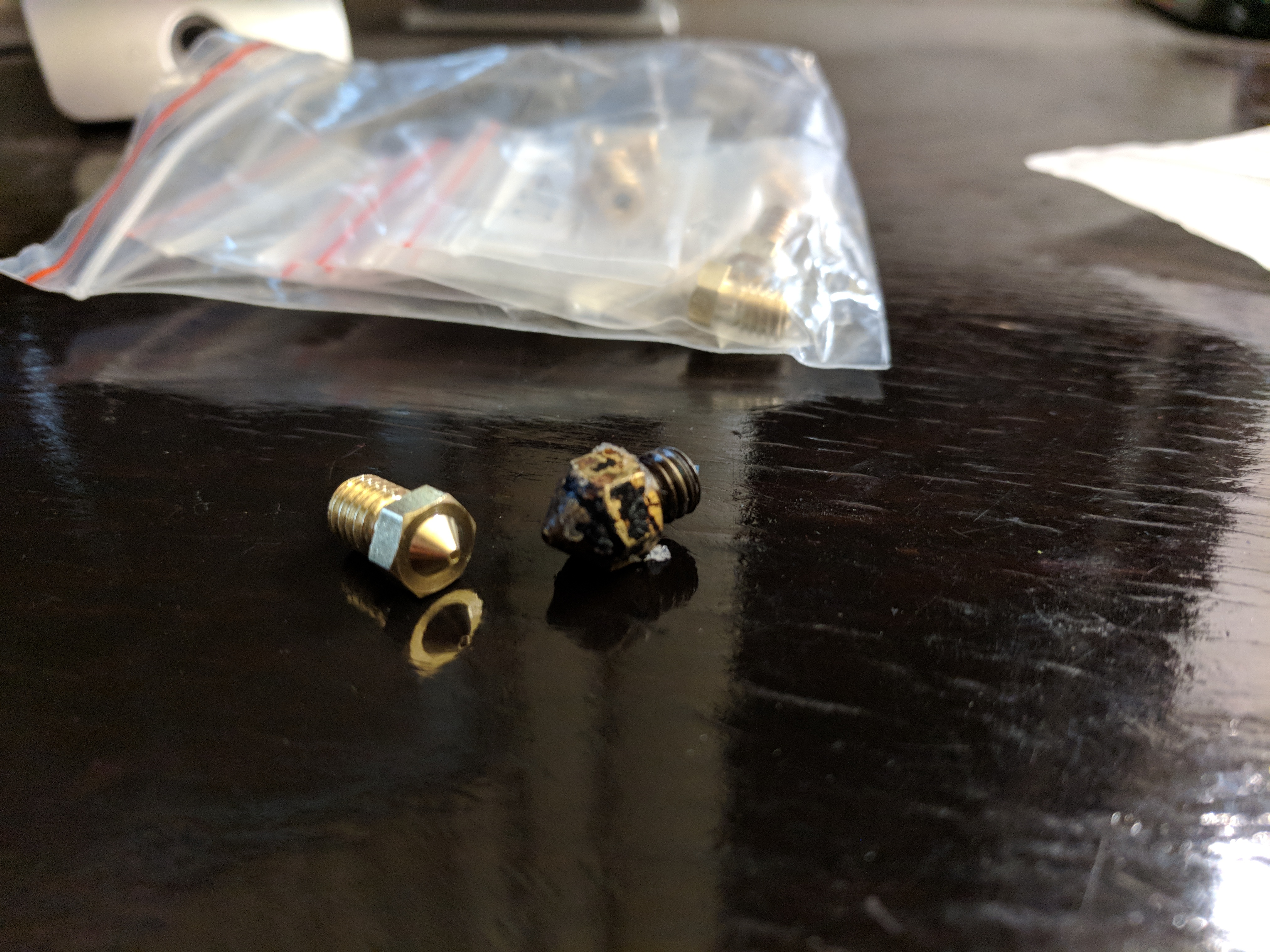
The set ordered:

The good news, the M6 threads match. The odd news, the hexagonal face is 7mm instead of 8mm. Bothersome - the “shoulder” around the orifice is narrower.

On very little basis, I propose a standard for nozzles. For 1.75mm filament, an M6 thread on the nozzle seems sufficient.

We need a standardized shoulder around the orifice to have predictable characteristics. I suspect we need a shoulder roughly of the size of the orifice. The shoulder forces the vertical dimension of the extruded plastic, and transfers thermal energy.

I recommend an 8mm hexagonal outer face for nozzles, as this allows for substantial shoulders on larger nozzles, while keeping the same vertical dimension.

In the reviews of the DeltaPrintr Mini, noted the recess on each nozzle face for a thermistor. Only logical the thermistor placement should be as close as possible to the point where plastic is extruded.

To be clear, I think the family of E3D inspired hot-ends are excellent if you are satisfied with slow, stately, majestic rates of extrusion. The large thermal mass evens and somewhat mitigates changes from varying rates of extrusion. Placing the thermistor embedded in the thermal mass, opposite the zone where plastic heats, means the over-taxed 8-bit controller will less bothered by varying rates of extrusion. (Never-mind the temperature variations in the extruded plastic.)

But if you want performance, you want to better know the actual temperature, in the instant. That means measuring at the closest point. That means allowing for a thermistor in the nozzle.

So … as standard, an M6 thread, an 8mm outer hexagon, a shoulder equal to the orifice, a fixed vertical distance between mount and nozzle-end, and allowance for a thermistor in the nozzle. Outfits meeting (or not) the community standard should be named (or shamed).

Substantial arguments welcomed. :slight_smile:

That’s a lot to take in? Here’s my two cents, wouldn’t it be easier to buy the direct replacement nozzel and hone out to the size you want? Rather than dealing with that?

you know “merlin” hotends?

Those are bargain bin nozzles, you can even see the left nozzle is not machines correctly centered.

Matterhacker.com has some speciality nozzles, stainless steel, hardened steels, a ruby lined. Give those a try.

The sharp tip nozzle with M6 thread and 7mm hex flats WAS the de facto standard (via open source Makerbot being the overwhelming market leader and cloning target) until the “mk10” cloner hot end and E3D came along. For years, the MBI nozzle was a demonstrably better performer than others such as the early E3D nozzles. Why? Because nozzle performance is much more about internal geometry than external. Specifically, going from ~2mm ID to 0.4mm ID in an abrupt transition from a standard 120 degree twist drill bit tip causes a LOT of resistance to flow. Viscoelastic polymers can’t change shape instantly so you need a more gradual taper (sharper point angle drill bit) or to step-drill in multiple smaller transitions. A smaller angle drill tip or stepped transition also allows for a shorter 0.4mm throat, which further helps with reducing viscous resistance to flow. E3D eventually figured that out… the cloners don’t care about print speed, which is why they don’t mind 4x2mm PTFE liners insulating all the way to the nozzle tip.

You often see crappy clone nozzles that cut corners and use cheaper 120 degree drill bits. Then they make the nozzle stubby and wide to shorten the orifice section because adding an intermediate drill step or using a sharper angle drill bit is more expensive. Pointy nozzles with proper internal geometry are a sign the manufacturer is NOT cutting corners to get cost down.

The size of the shoulder around the orifice is a matter of preference. Specifically, sharper nozzle tips work better for certain types of fine detail work, because they don’t smear and drag the plastic around as much, and they don’t radiate/conduct as much heat to freshly-deposited plastic that you want to cool quickly to lock in geometry. A larger shoulder works better when your extrusion strands are a lot wider than the nozzle orifice, or you want the flattest roof layers possible.

As for thermistor placement… temp control is basically zero processor load; you only have to run the PID loop every 0.05-0.5 seconds or so. The time constant of a bare glass bead thermistor is about half a second so you’re wasting time reading any more often than 5-10x faster than that. (Boards that have to heavily oversample to cancel ADC noise like the Smoothieboard being an arguable exception, but then the oversample filtering kind of wrecks your sensing time anyway so it’s moot.)

What IS a temp stability problem is placing the heater too far away from the thermistor. The thermistor needs to “see” heater action with minimal delay or the hot end temp will oscillate. That’s a mathematical fact of feedback loops — excessive dead time leads to a phase lag and oscillatory behavior. Specifically, the farther the thermistor is from the heater (in terms of conduction sensing delay time) the lower you have to set the PID gains to prevent oscillation, and thus you get slower PID response to error and eliminate much of the point of sensing at the nozzle tip.

Hardened is for abrasive filaments. The best are copper as they have a minimal thermal resistance. Also, I prefer massive nozzles, as tiny ones react to the slightest draft from a passing by person.

@Alex_Koukarine Copper corrodes and is heavy and expensive and soft. Brass is a perfectly fine material for this. It machines well, holds threads well, and is cheap. Conductivity of heat into the filament itself is so low compared to brass that there’s minimal gain from anything more conductive than brass.

These other nozzles have been developed because not everybody prints in ABS or PLA. It may not be required for a one off print, but for multiple prints or long term, or a special effect, it is about matching the printer nozzle to the correct filament.

@Ryan_Carlyle that being said, the ideal system is two thermistors - one in the thermal mass to be PID controlled, and one at the tip to (at a slower rate) measure the heat loss from mass to tip and feed back that to the target temp of the thermal mass PID

@Jason_McMullan Yes, good point, that is a very good approach. Although I do personally question whether we should be sensing at the nozzle TIP or trying to get deeper inside the hot end where the filament is actively melting. For example, if you extrude too fast and a slug of semisolid cold filament reaches the nozzle, you’ve already jammed and cause a problem before the nozzle tip sensor sees anything.

why not using a multi zone nozzle? A preheat zone to make the filament soft (~180°C) and a hot tip (~230°C) to ensure a very short time the filament is at hot temp.

@Ulrich_Baer heat rises, and rises up the feed path, so no preheating is required. The filament gets exposed to too much heat as it is, and it slumps or expands in the print head, once it expands past its manufactured limits i.e. 1.75mm, or 3mm it plugs up and blocks the feed.

@MidnightVisions This is why i said “multiple zones” . So the heat will not rise up the feed path und by controlling the zones you would only need to add a little energy at the tip. Think of a normal hotend running at low temp and a secondary annular insulated heater for just the last 2mm bringing the temp to 230°. So your filament is only exposed for a very short time to the high heat. Also when using such a small zone you can regulate this much more controled as there is little thermal mass and without preheating you will not get enough energy through that small contact surface.

@Ulrich_Baer @MidnightVisions if anything, I’d rather have a HIGHER temp in the upper part of the hot block than nozzle, to facilitate rapid heat transfer into the filament. That way, in the zone where cool filament is entering and then is actively melting, it has the maximum possible delta-T for improved heat flux. Then the nozzle has the correct extrusion temp for proper adhesion, ooze control, etc.

I wouldn’t do that with PVA (since it pyrolyzes to tar) but it would work really well for something well-behaved like ABS that can tolerate much higher temperatures than we typically print it.

Incidentally, I’m one of the weirdos that wants a big chunky hot block for maximum temp stability, not a tiny little thing for minimum mass. We’re trying to keep extrusion temp CONSTANT and the way you do that is by maximizing residence time (ie longer melt zone) and maximizing the heat capacity (“thermal mass”) of the hot end below the heat break.

It’s really, really easy for a PID loop to keep a big hot block temp steady, even if your sensor or heater placement isn’t ideal. If your hot block temp is steady, and reasonably insulated to keep nozzle temp near hot block temp, you’re done and you’ll get good results.

But it’s literally impossible for a PID feedback loop reading a 0.6-second-time-constant sensor, powering a heater with a 3 second heat conduction dead time, to keep up with the exact heat flux needs of an extrusion flow rate that can vary by a factor of 10x in a tenth of a second. The smaller the thermal mass of the hot end / nozzle, the more exactly the PID loop has to track the melting energy needs of the filament. If you want to actively vary heater power to keep up with melt heat requirements as the printer constantly changes from high-speed coasting to acceleration-slowdown-rich detail geometry, you’re going to need feed-forward heater control to have a prayer.

The smaller your hot end thermal mass is relative to the range of variability in your melt heat flux demand, the less stable your temps will be.

@Ryan_Carlyle yes maybe you would need a different heater like IR- radiation (Halogen lamp) or an induction coil. Or you have a liquid heater pumping hot oil, which would allow high constant thermal flux. (as used on professional machines)

@Ulrich_Baer still doesn’t fix the fact that the filament itself is an insulator… we’re limited by conduction through the ~1mm radius of the filament through the 2mm ID melt zone.

@Ryan_Carlyle Doing that will cause blockages, especially with ABS. The filaments must be uniform and solid between the extruder and nozzle because its the metering of the filament width through the nozzle that determines the output volume. If it is not consistent then the output volume will also not be consistent. The only point of the hot end you want hot is the nozzle, and inner chamber, with the filament melting upon contact with the inner chamber. Heat creep up the feed path causes the filament to mush, widen and then there is inconsistent flow. The feed bolt will then strip the filament from the extra friction, and debris will eventually contribute to a total blockage.

@Ryan_Carlyle yes i know which was why i came up with a pre-heating zone.

@MidnightVisions ummm, no, that’s not an even remotely accurate description of what happens. The behavior here is well-documented in Stratasys patent literature and easily confirmed by cold-pulling filament out of a hot end at the end of a print to look at the shape.

Filament starts melting right at the heat break between the hot block and cold zone heat sink. That forms a transition zone or “cap zone” where a ring (eccentric ring almost a crescent really) of highly viscous semi-melt tries to flow back up the heat break, surrounds the incoming filament, and is heavily sheared against the heat break walls by downward filament motion. That viscous shear generates a pressure seal that contains the very high pressures in the melt zone above the nozzle.

Injection of solid fresh cold filament into the cap zone sealing area is what meters flow and generates melt pool pressure. It’s a positive displacement piston pump, with pressure contained by a dynamic viscous seal.

The equilibrium position of that seal depends on the temperature profile across the cold zone, transition zone, and hot zone, and how that relates to heating of the incoming filament through its melting and viscosity curve. Typically the cap zone is at the very top of the hot block. High extrusion rates (particularly with PTFE liners) push the cap zone down below the heat break into the hot block and closer to the nozzle, because the incoming cold filament isn’t heated as fast meaning the cooler cap zone has higher viscosity, so it gets pushed down by filament motion harder than pressure tries to flow it back up. That cap zone motion doesn’t really cause any issues though, aside from a little bit of extrusion flow lag. (Part of what Pressure Advance firmware code deals with.) The biggest issue with high flow rates is the unmelted core of the filament hitting the taper to the nozzle orifice as a solid, and thus acting like a check valve to shut off flow. Simple reduced extrusion temp leading to poor adhesion is also an issue, but less likely to abruptly strip the drive hob grip and fail the print.

Hot end jams caused by heat creep occur when filament above the glass transition temp (soft and possibly sticky) enters the cold zone by whatever mechanism (retraction, heat conduction, backflow up the heat break, etc), gets mushed against the walls by filament pushing pressure, then cools and solidifies in place. That’s largely a matter of cold zone cooling to keep filament solid, and almost entirely unrelated to the temperature profile below the heat break.