Installing the Cohesion3D LaserBoard into a Full Spectrum MLE-40 4th Gen Laser is easier than you may think. There were two different controllers and three different configurations used in this model and I’ll cover each one as I go.
You’ll need a small flat screwdriver for attaching some wires.
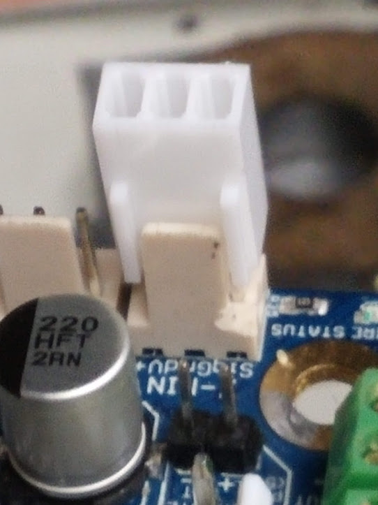
This is the first controller used in the early models and comes in two pieces with connectors that plug directly into the board. You will only be able to plug the stepper motors directly into the LaserBoard, the rest will need to be connected with the screw terminals.
If you have this controller, proceed to LIMIT SWITCHES .

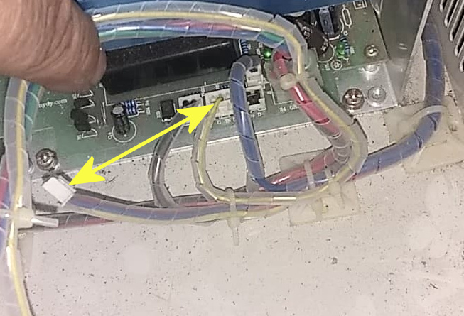
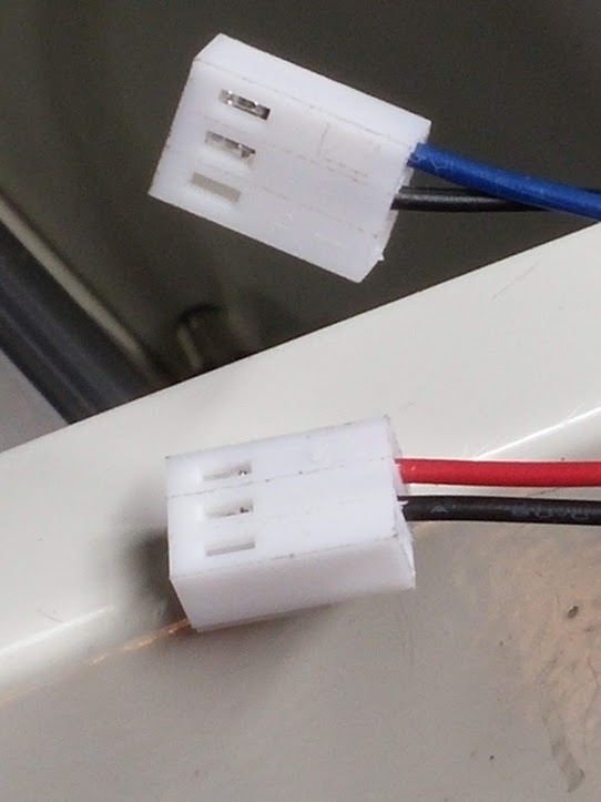
This is the second controller version with two possible configurations, one with the current controlled by the dial on the panel and one with the current controlled by software. They generally left the potentiometer mounted in these units with the cable unplugged and laying on the bottom near the laser power supply. All you’ll need to do is unplug the wire going to your old board and plug the one laying free in its place, as shown below. You’ll use the dial to set your maximum safe current, which is usually around 15mA to 16mA and LightBurn will control 0-100% of your set limit.
Photo courtesy of Chris Cecchini.
Simply swap these two plugs and set the current to 15mA. Photo courtesy of Jeff Gray.
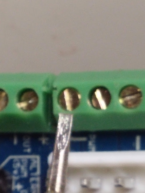
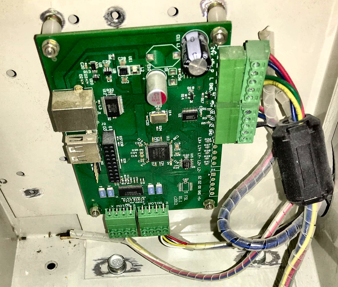
The connector ends on the wires are cut off on this model controller, but it’s no problem for the LaserBoard since it has screw terminals for the stepper motor wires and laser firing control.
Make sure to note the X and Y cables and place the wires accordingly.
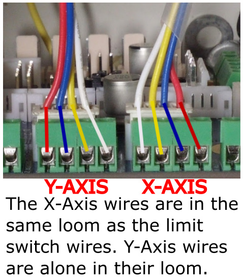
Your unit may also wire like this.
Photo courtesy of Chris Cecchini.

LIMIT SWITCHES:
In order to properly mount your limit switch wires, you’ll need to purchase inexpensive 3 pin Molex KK connector ends. These are very easy to install and can be purchased at the Cohesion3D online store. https://cohesion3d.com/shop/peripherals/connector-pack-for-cohesion3d-boards/
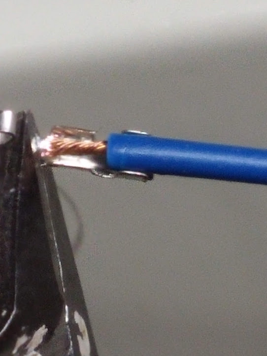
Your limit switch wires are going to be the thicker red, blue and two black pieces all in the same wire loom. The black wires should go to the center pins, which is ground and the colored wires will go to the signal, NOT the V+. The red wire is for your X-Axis switch and the blue wire is for your Y-Axis switch. These switches are normally closed, and if you would like to pair them, you can use a meter to check continuity. When the switch is triggered, the circuit becomes open and that’s what signals the LaserBoard that it’s in the homed position.
I recommend using a multimeter to pair the wires so any future troubleshooting will be smoother, but is not necessary if you place the black wires in the center pins (ground) on both plugs since the grounds are all tied in. You’ll need to strip the ends of the wires, crimp them in place and then insert them into the plug. Note the position of the clip going into the plug.
Match the size to crimp.
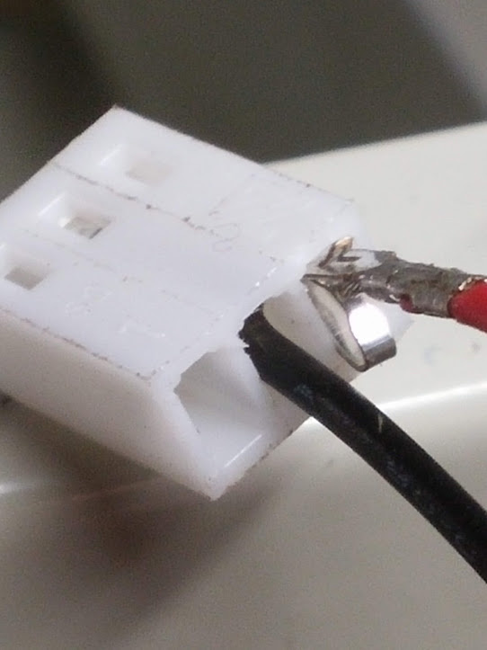
Carefully insert them into the plug housing. Make sure to place them exactly as I have them here.

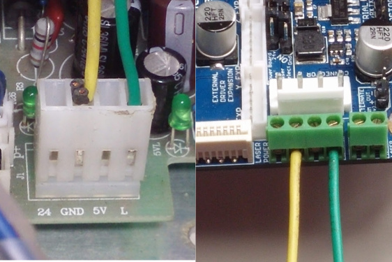
The Cohesion3D LaserBoard comes with a high quality (UL Listed) power supply that eliminates the 24v and 5v requirement from the laser power supply and requires only two wires, the laser fire control and ground. You can remove the 24v and 5v wires altogether as shown or you can use them for your lighting and diode pointer if your unit has one.
Do not attempt to utilize any power from the LaserBoard except otherwise noted in the LaserBoard documentation on "Air Assist Control."LaserBoard Air Assist Control
Connecting anything else can damage it.
The only two wires needed for controlling the firing. L to the screw terminal shown, which is marked “PWM” on mine (for pulse width modulation power control) and the ground.
Using the 5v out on laser power supply to power the diode pointer is perfectly acceptable since that was the default setup, but there is no longer a need for these wires to connect into the controller and caution is advised to keep them isolated from shorting. The black wires were already cut from my ground, but you’ll need them if you choose to use the laser power supply for lighting or the diode pointer.
I used one existing hole, then marked and drilled the other three.
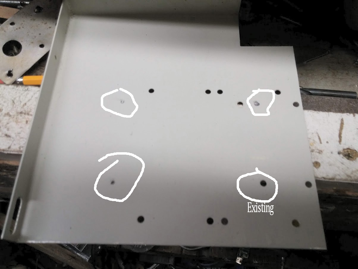
Here’s the final install.
