Hello. I’m noticing that my laser beam is more powerful as the head aproaches the lower edge of the bed. I think this could be a mirror alignment issue. Correct me if I’m wrong.
The focal distance is the same everywhere, so I discarded that.
I know there is a kind of tool for measuring laser power but it’s not easy to get here neither a cheap tool.
Is there an easy and cheap way to measure the laser power?
Now I’m handling this cutting little circles in different parts of the bed but it’s a very rudimental way and take a lot of time.
Thank you
Generally the power reading device of a laser is frequency dependent.
Might want to complete your profile so we can see what kind of machine you are using…
![]()
1 Like
alignment 100%
what do you expect from such tool ?
are you after a numeric value ?
The other way is to make a ramp test, and compare the result with your expectation. you also got the limit of your system with the fitted tube.
my 2 cts
1 Like
Yes, I’m going with the mirrors alignment. I just wanted to prove the power a little more to be sure and don’t mess the alignment, but anyway I will need to learn how to do this at some point.
The optical path and focus is most important… The focus make these work…
Since you have a co2, this is a good video on how this works…
I have a Mahoney 100W meter and a doHICky from Russ Sadler… probably the best you can pick up… Here’s his video on it …

Have fun…
![]()
1 Like

The laser beam points this spot on every corner. So it’s aligned. The problem is this mirrors supports don’t have any altitude regulator. The third and second mirrors are both aligned horizontally but they need to be positioned a little higher.
But going back to the main problem. This is bad because the desaligmen theory is discarded. Power should be the same at any position even if the spot is not centered, it is always pointing the same place.
The only idea that comes to my mind is to supplement the screws that hold the mirror supports with washers. But maybe I will need larger screws…
That is not in the center… is the mirror not centered in the hole?
I guess, to me it doesn’t look aligned… also, doesn’t appear to be in TEM00 resonance. Is this multiple pulses from the corners or just a single pulse?
It’s also a very big beam…
Many machines have a 4th corner anomaly. Many times, if properly aligned elsewhere, it can be correct by a very very fine adjustment of m1.
Good luck
![]()
1 Like
And I cringe every time I see someone putting tape over a mirror to mark the laser beam.
It does not look like it burned through on the laser head but be warned, there is very sticky material on the back of that tape and when you heat it with a laser or worst, burn through it you have a high probability that melted glue with spatter onto your mirror and it’ll be very difficult to get cleaned off.
If your mirrors are aligned, check that the beam is not clipping the edge of the nozzle as it exits the nozzle. Check this at all 4 corners of your machine. The beam should be exiting the nozzle dead center at every corner.
1 Like
And I cringe every time I see someone putting tape over a mirror to mark the laser beam
But how should I do it if not with tape?
At the very least put something like a coin on the back side of the tape at the opening to the mirror. Paper targets are also used but as you probably guessed they either need holders made or taping on the sides.
1 Like
I was thinking, Wouldn’t be better to lift the mirror up instead of suplement the hole structure with washers? The input beam would be not centered but the reflecting point would.

1 Like
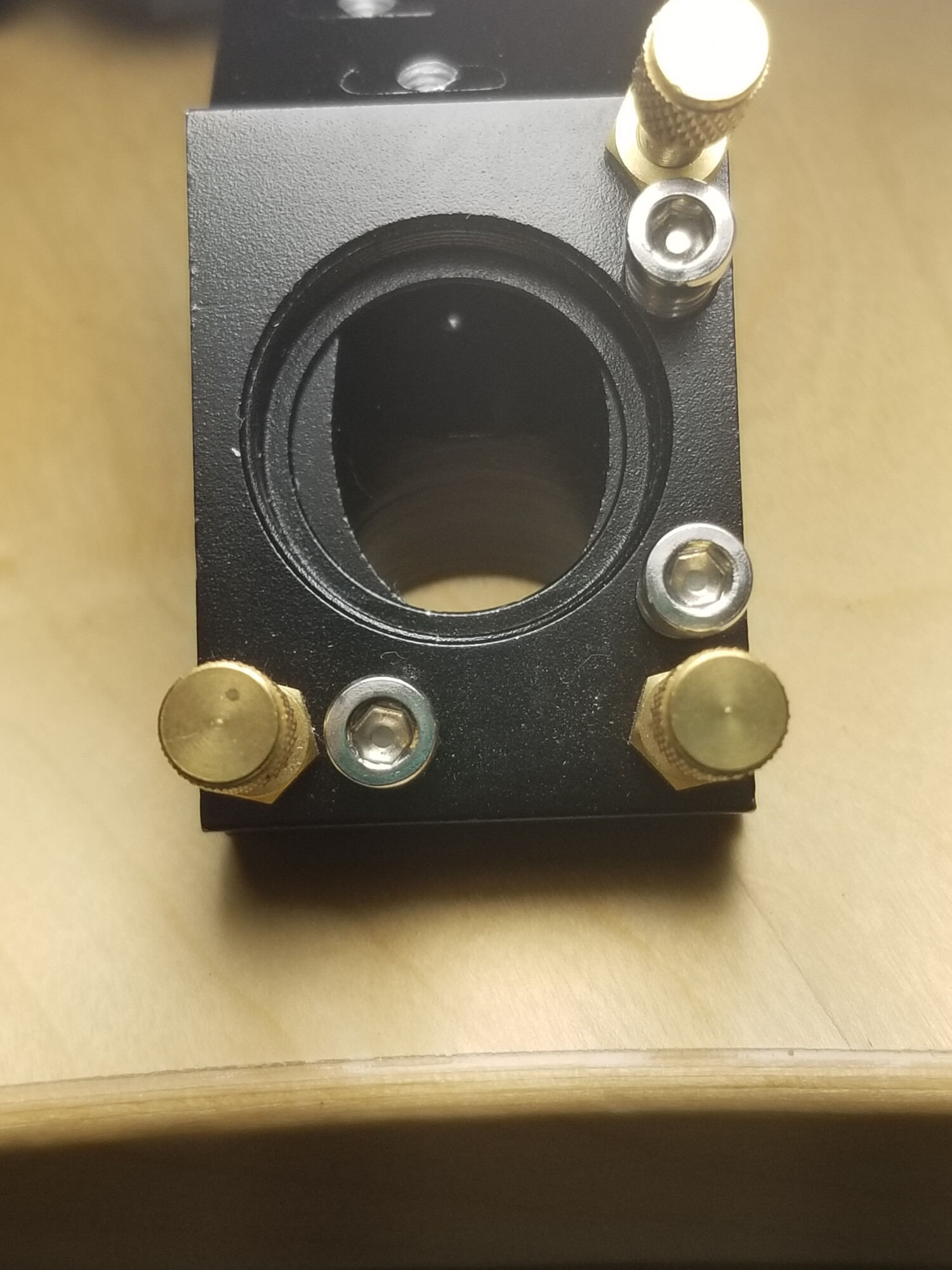
This is why many of us has dumped the commercial head and replaced it with one that has a Z adjustment…
There is also a misleading part about some of these heads and holes… if you look at mine, it doesn’t take any instruments to tell the mirror is not in the middle of the hole.
My mirror holders are a bit different… I cut out watercolor paper and mark it. Takes low power. Also no need to burn these thing. The lighter the touch the easier they are to see.
Good luck
![]()
2 Likes
I have spent much of the last few months honing my K40 to be as efficient as possible and creating a maintenance program for small production cutting so you may find a few things here helpful. The issues I wanted to resolve were:
- The poor design of the gantry cradle where there is no easy way to adjust the head in a vertical direction and is generally hard to adjust.
- Laser alignment efficiency
- Laser cutting efficiency.
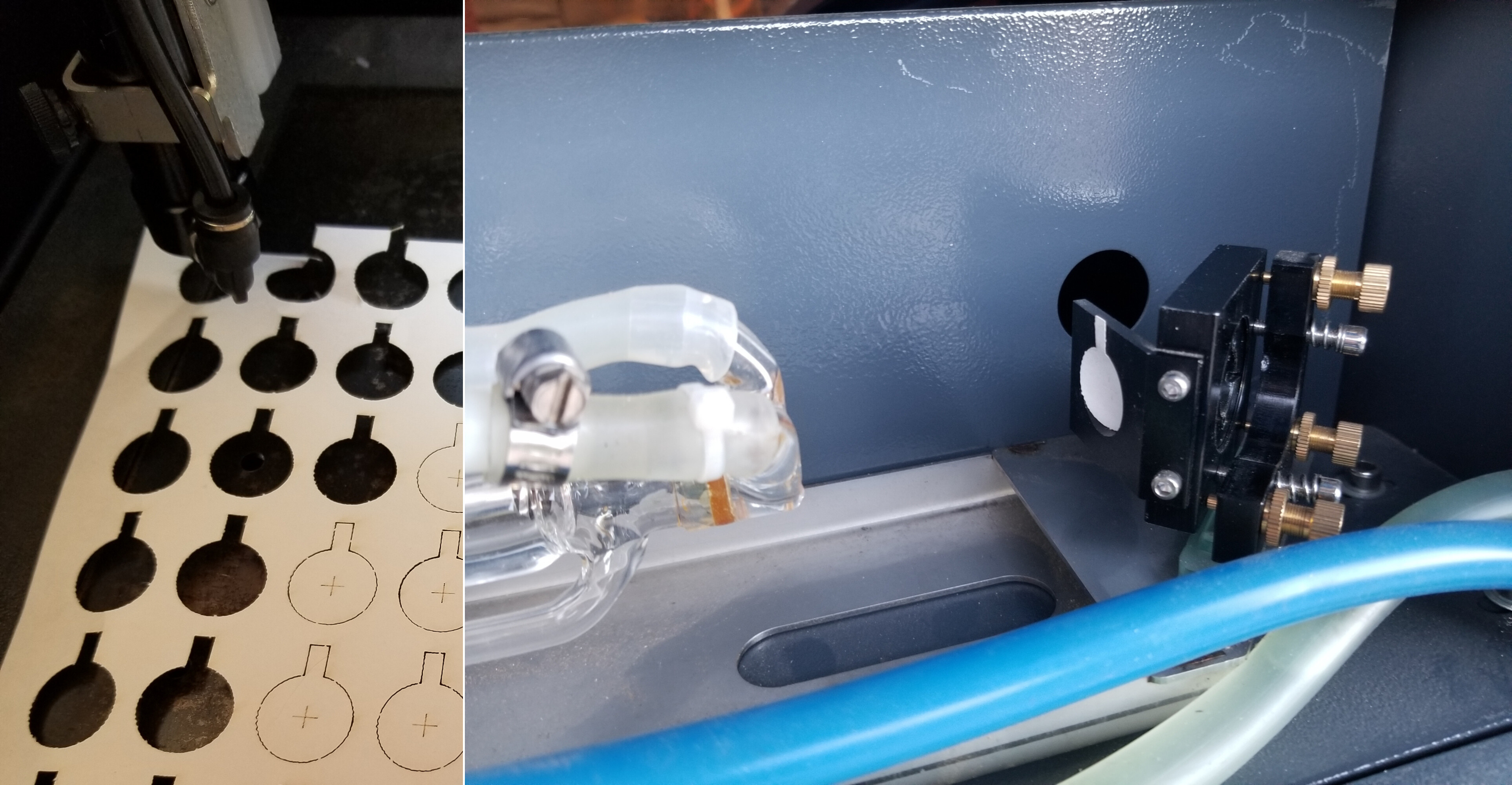
Linear Rail – I decided to ditch the gantry cradle and upgrade to a linear rail. This meant I then needed to design a new head bracket and holder which means I could include adjustment for both the y and z direction. As you can see from the pic the linear rail is fixed to the top of the gantry with the printed bracket. The head holder is then attached to the bracket giving both y and z direction adjustments. I have included my red dots into the latest iteration, and I will incorporate my side air assist tube in due course. This change has made the machine much more efficient and serviceable.

Laser Alignment Efficiency – When I first bought the machine, I could not get on with using masking tape over the mirrors to determine the position of the beam, so I printed these tools, one for the fixed and y axis mirrors and one for the stock laser head. As @dougl has pointed out, simply placing tape over the mirror hole could allow ingress onto the mirror and is extremely cumbersome anyway. By simply designing 2 printed tools to slot over the mirrors and the head then sticking a ready-made and correctly positioned printed target label on them simplifies regular alignment and checking with full protection of the mirrors. Other than initial setting-up I have not needed to adjust the fixed or y axis mirrors, but I do regularly use the head tool by carrying out what I call a 4-corner alignment test and you can see the results of all 4 spots on a single target below and it only takes around a minute to carry out if all is aligned.


Laser Cutting Efficiency – I noted in your post that there was a loss of power in one corner, and I found the same when I first produced the new bracket and yes, as noted by @dougl, it was that although the 4-corner alignment test was fine, the beam was not vertical on the head due to a slight misalignment of the head in the vertical direction. Although I can adjust for this I would like to find a laser head that has an adjustable mirror but there does not seem any short length heads for the K40. Does anyone know of a suitable candidate?
What I have done is to create a 4-point cutting test by cutting a 3mm ply template from which I cut out 42 x 25mm square tiles which then holds 4 slot-in tiles and cuts a 15mm square in each corner. This minimises the amount of wood cut and takes around a minute to run and, in my case, over time I do get slight variations in my bed height which I can then adjust at each corner if necessary.


These processes have improved efficiency, serviceability and consistency from a small production perspective.
5 Likes
Pretty nice solution for the K40 issues…
I might mention that most of these machines home on at least one of the axes by the gantry position.
Mine homes by the Y gantry position. If I move the head in the Y axes direction I no longer can use absolute coortdinates that are set up for my jigs, as it will be off by the Y correction of the head change. Also affecting your work area by that amount.
I have lots of jigs and items that depend on a repeatable home operation.
My m2 mirror is adjustable in the Y direction which alleviates this issue and allows a front-back axes adjustment for striking m3.
You can see both here…

However, a nice solution to a sticky wicket…
![]()
3 Likes
Nice. I did consider changing my m2 mirror mount but I don’t seem to need to adjust it. What I am interested in is to be able to adjust the m3 mirror so it is always vertically aligned to the bed. It looks like you designed your own adjustable laser head.
Not really… It’s one of the many Russ Sadler creations…

![]()
and CloudRay used to sell them but I was not able to find it. If you really want it, Russ posted the DXF files somewhere and companies like Send-Cut-Send can make the flat stock for you for pretty cheap. You’d need to tap holes and do some simple bending so it’s possible with only hand tools.
Since my last post and the latest version of my new laser head assembly, I have encountered problems in fully cutting through in the bottom right corner of the bed, and I have confirmed the issue is vertical alignment. As you can see the 4-corner alignment test shows the spots are not fully central but are close enough. For the first time I tried a vertical 4-corner laser head test by placing a fixed mirror tool target on the bottom of my stock laser head and as you can see the spots are right on the edge. This is an x-axis rotation problem and I have no way to rotate on this axis so I tried to correct with a shim which so far has thrown out my overall alignment so I will need to work on an interim solution. I think I could have corrected a y-axis rotational problem. The conclusion is that I really do need a fully adjustable laser head mirror going forward.

So, many thanks for your input. I have reviewed the video and downloaded the files, but I would only need the laser head tube and mirror assembly which would give me full x and y vertical adjustment as I could fashion it to attach to my linear rail but I cannot see where to source these parts, so this Cloudray laser head looks like it may be the solution. My concern is it may be too tall? The information suggests it is suitable for the K40 and the tube length looks around the same as the one in the video. While I am at it, I would upgrade the mirror and lens.

It is super critical that the optical path framing is square AND in the same plane. Not 4 or 5 mm off being close enough but less than 1mm off( +/-0.5mm ) is what I might call close enough for the small things I do and it might not be enough if I start doing full bed engravings/cutting.
Once the optical path and motion framing are square and level, then shimming it so that it is level with the bed is the last step. Otherwise the beam will be dancing in circles as it exits the focus lens across the X and Y axis range.
1 Like