Hey,
A while ago I tried out 3D printing and it became a hobby of mine. Now I wanted to try out lasers.
Similar to my first 3D printer, I bought a cheap one so potential mistakes don’t hurt to bad.
Assembling the kits also helped me understand the inner workings of those machines.
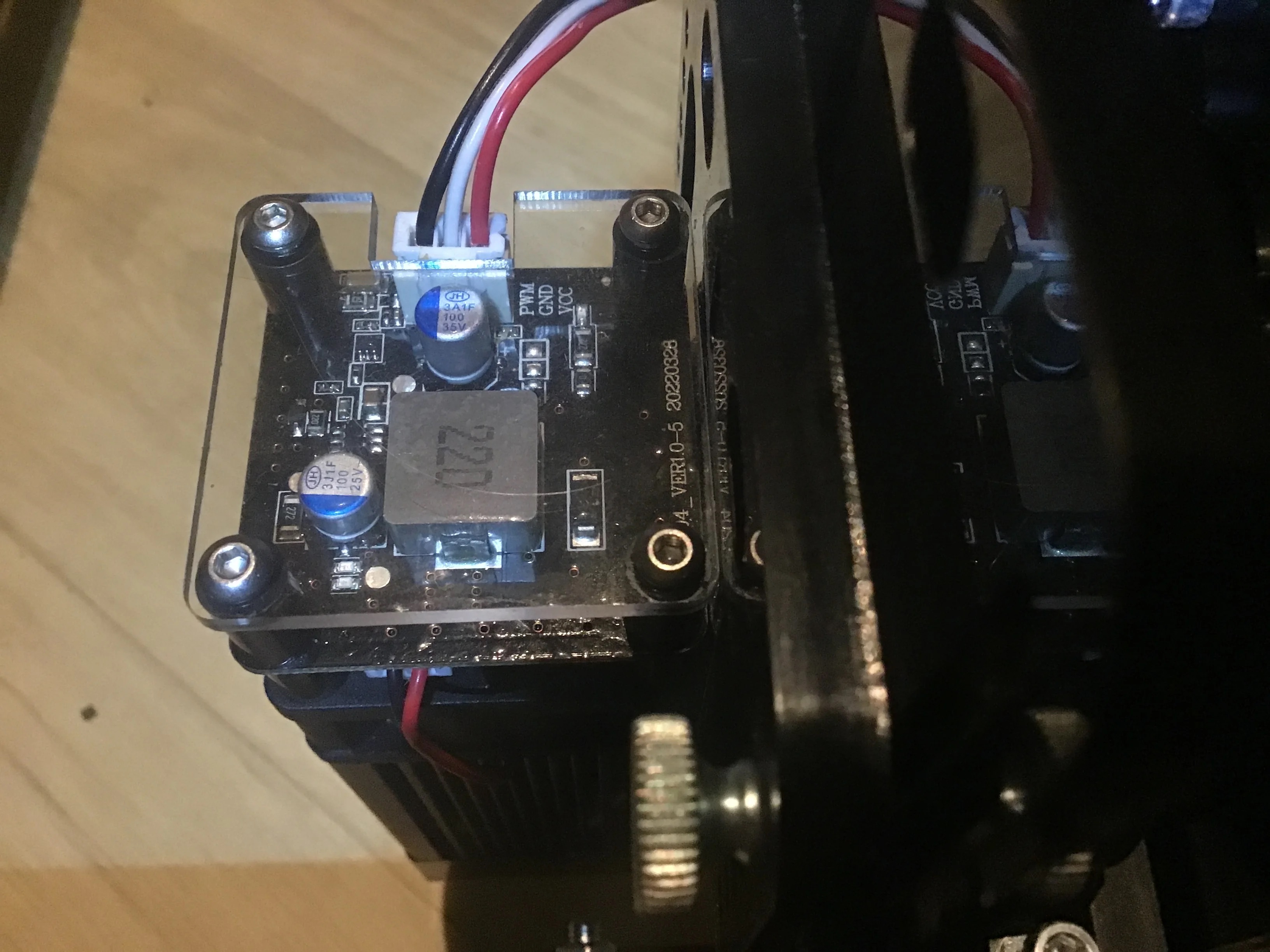
Problem is, the laser doesn’t emit any lasers. A pretty obvious flaw which im still baffled by is that the 3 pin connectors of the control board and the laser module don’t have the same sequence. Before some lights turned on and the fan for the air assist spun a bit. When I “fixed” the sequence the fan spun up rapidly. Maybe the difference between the 5 and 12 V line. In either configuration, the laser stays dark.
I checked all the wires and connections and the stepper motors and endstops work perfectly.
Hopefully I just missed an easy fix.
I’m grateful for any help on this.
Additional Information:
I got myself a Laser Tree LT-40W-F23 as a Laser module and a TwoWin 6550 as a CNC base. Both should work at 12 V with 3 pin connectors.
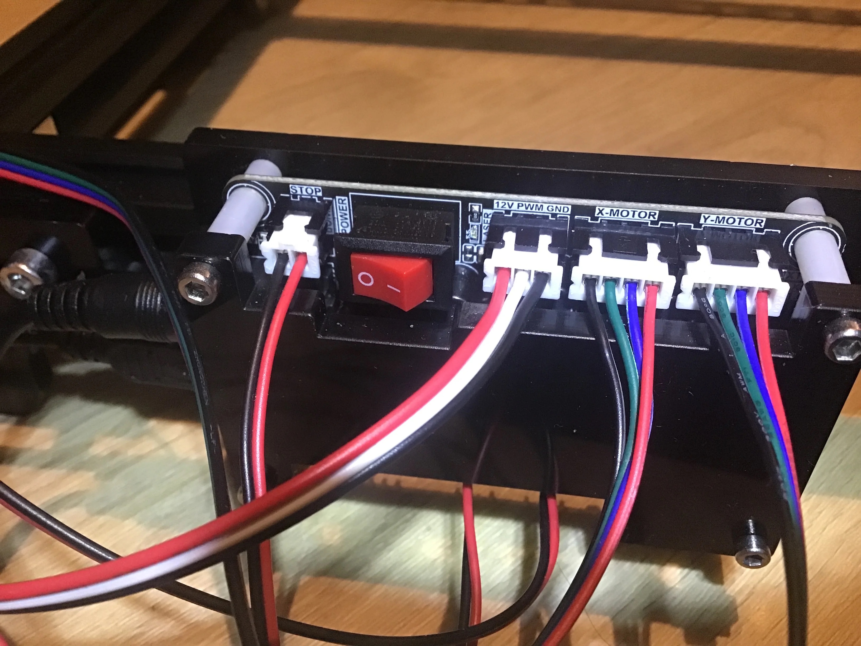
Do these photos reflect before or after you fixed the wiring?
If this is after, the GND and PWM are reversed on the laser end.
I would start by measuring the 12v going to the laser.
The fan on these modules is hard wired; it runs all the time when 12v is applied, the laser itself is a separate circuit.
If you powered on the machine like this it is quite possible you have blown the PWM pin on controller up by pulling it close to 12v via the fan; unless it is isolated/protected properly on the controller board.
Similarly the PWM pin on the laser will have had a negative voltage on it (relative to the laser modules GND) and may not have survived; again depending on how well it is protected in the module.
Edit:
Neither of these has a quick fix ![]() , You need to start by debugging them separately.
, You need to start by debugging them separately.
Does the laser fire with 12v applied to the power pins and the PWM line pulled high via a resistor?
- Lots of these module already have the pull-up resistor on-board, and the laser fires automatically unless the PWM pin is connected to GND.
- Take care where the laser is pointed when doing this!
Do you have a PWM meter or scope? If you set the laser on and at 0%, 50% and 100% power do you see a corresponding signal on the PWM line?
- If you just have a multimeter, measure the GND-PWM voltage and you should see a difference with this too.
If the laser module is broken, it may be possible to replace just the controller board.
- The laser diode itself is unlikely to have been damaged.
If the controller PWM output is broken (but the controller runs otherwise) it may be possible to use an alternate pin; either a spare heater/fan pin, or re-purpose another PWM pin for the job.
I changed the order in a spare cable by changing the sequence in the middle of the cables so I can still use the connectors.
Wow thanks for your detailed answer. I will try it tomorrow and keep you guys posted.
I’ve never asked anything myself in forums.
I doubt you damaged the board. The pwm pin can take 12V applied to it… many of these use an optical isolator which gives them more flexibility on the supply to this pin.
Even if you swapped ground and pwm, it should reverse bias the optical isolator and no current should flow… hopefully, no resultant damage.
I assume this is the animal?
LT-40W-AA_User_Manual.pdf (2.1 MB)
![]()
Ok
I tried it out.
The Laser Module and its small board is totally fine.
As it turns out, PWM of the control board didn’t output any voltage, even when it should. VCC was fine.
Sadly I don’t have any other PWM outputs on this board.
Anywhere to go from here?
It’s possible you damaged the control board with the wiring swap.
Most of these outputs used for laser power (pwm) come directly from the cpu, there is no buffering of the signal, wiring one to ground may have caused it’s demise, as there is no current limiting on these that I am aware of.
Ensure the software is configured… I don’t know what you use… In Lightburn it’s the $30 variable on the machine has to match the S-value Max in the Device settings. I think $31 needs to be zero.
![]()
You can try tracing backward the pwm signal on the board and see if there is any device between the CPU and pwm output. If so you could look at the input to that device.
Hey,
sorry for the radio silence. I had some other personal issue.
One thing that bugs me is the fact that the laser manual calls for 0/3-12V on the PMW line, whereas the board only delivers 5V on PMW. Could this be the problem?
And if so…
Are there any boards that output the right PMW signal?
Standard ttl logic levels allow a high state to, generally speaking, to be over the 1/2 ttl threshold.
They use 3V to 12V, this allows a 3.3V device to directly drive the module into an on state…
It’s usually some kind of optical isolation so if you use a 3.3V, 5V or 12V signal it should work, assuming the 12V signal drops below the 3V high state.
![]()