I have been making some slow progress on my Laser cutter/engraver build and I have the frame assembled with the X/Y motion working. In wanting to keep the wiring as neat as possible I have decided to use a ribbon cable to connect everything back to the Smoothieboard and this is what I have come up with…
The 26 way ribbon will feed to a PCB mounted behind the X motor, this has the connectors for the X motor, x/y limit switches, a spare 12v connector and then a 16 way connector to feed to another PCB mounter behind the gantry. The Smoothieboard will be mounted above the frame, so that the only movement on the 26 way ribbon cable will be in the y direction. Here is the x connector PCB…
I am going to tape the 16 way ribbon cable on the back of the x axis extrusion, in a similar fashion to my Artillery X1 3d printer.
I also plan to add some z axis movement, which will give me more options on what I can do with the machine and in trying to keep the weight down I would like to use a 12V 24BYJ48 motor for the Z axis. Because the motor is geared I am thinking that I will need to run at full steps but the microstepping is fixed on the Smoothieboard so I have decided to add an external A4988 driver board as well.
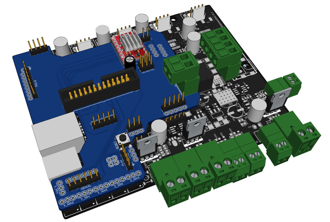
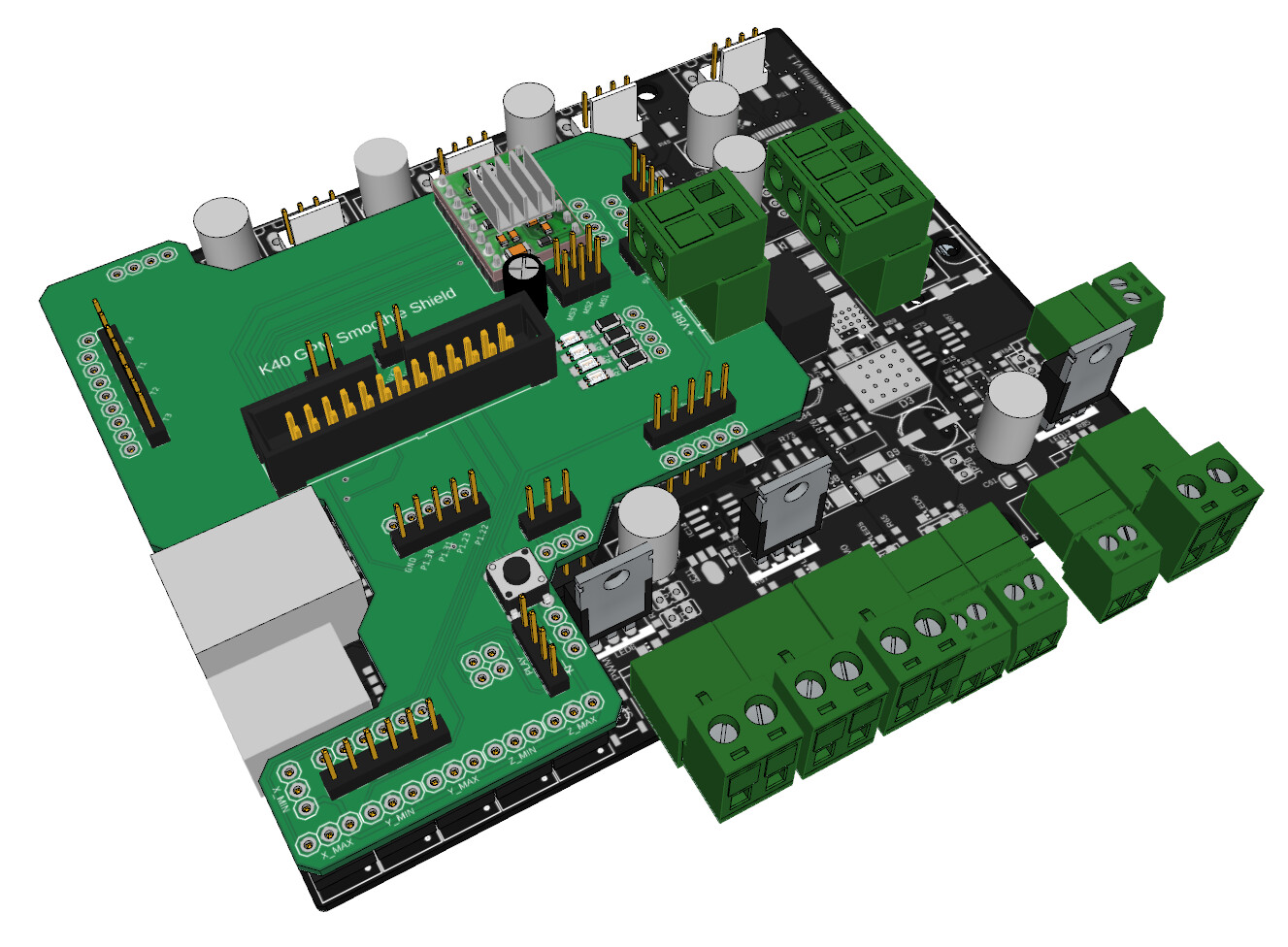
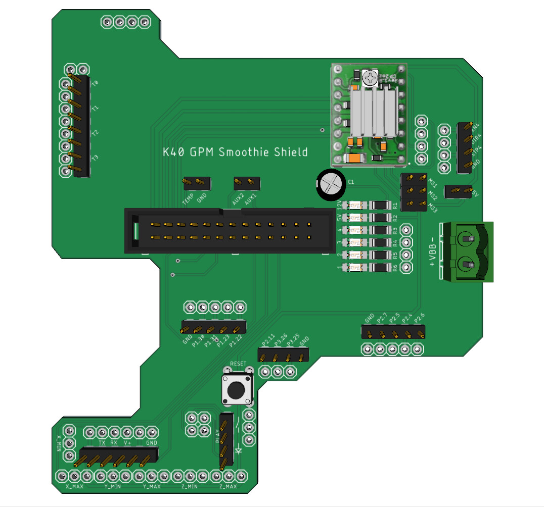
Here is a 3d model of the shield in place on the Smoothieboard…
I have passed through a bunch of pins for me to use for switches, plus the serial connection as I plan to add some form of control panel in the future.
So can anyone see any glaring errors or have any suggestions/feedback. I am not an expert in PCB design or electronics, and as we all know sometimes a little knowledge is dangerous
Aside from that can the thermistor pins & unused motor pins be used for input for the switch module?.
This is a diode laser build which is going to fit in an old K40 enclosure, which is why I called it K40 Blue. So there will be no coolant or pointer needed. The laser module does have a temperature sensor built in though, which would be useful to monitor. I am mainly concerned with getting all the required connections from the laser module, motors & limit switches back to the Smoothieboard. Anything else, such as safety switches, LED lighting control and panel buttons will be connected to the headers brought out on the shield.
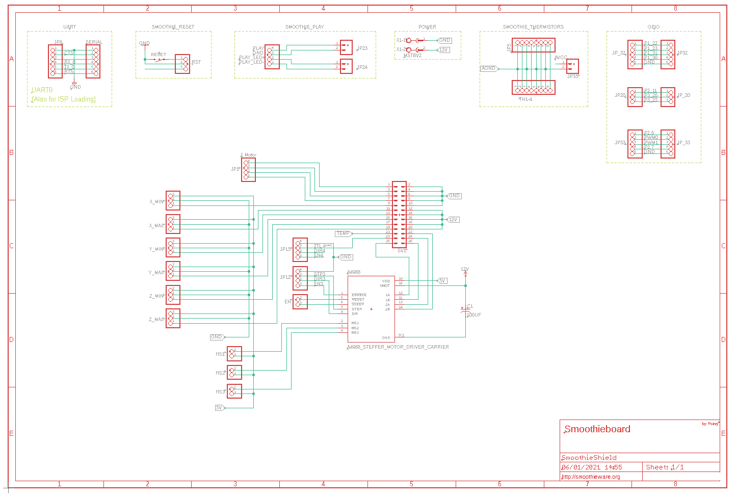
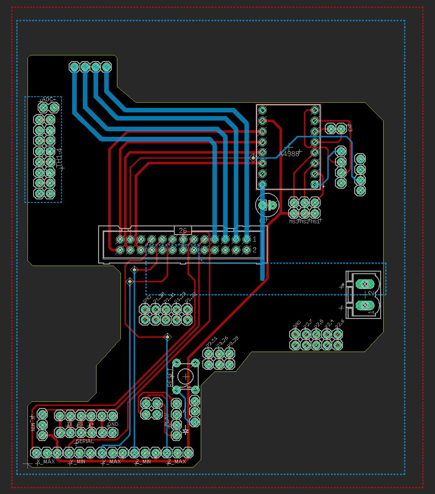
The schematics/pcbs were designed by me using Autodesk Eagle, which is a little clunky until you get used to it. (I did use the Smoothieboard Eagle source files to get all the connectors in the correct place though)
Oh man this is really really cool!
When you have it built, tested, and published, tell me and I’ll make sure to promote this around the community.
I designed something similar (general purpose instead of for K40) two years ago but never got around to actually publishing it, so glad you are doing this!
Actually after I posted this, I decided that if I can design a sensible mounting mechanism, that I could maybe do some very light engraving using something like a 775 motor. I have since modified the Laser connector PCB and added an optional mosfet to the pwm laser signal, that should allow me to drive a small motor/spindle.
Ok, so clearly I shouldn’t work on something early in the morning until I have had at least 4 cups of coffee. I am not sure why I thought the A4988 was mirrored.
Anyway, I have been finalizing the design of the shield and it occurred to me that as the shield is covering LEDS 1-4, that I should perhaps bring them through to the shield using jp29…
I think I am just about ready to order the PCB’s now. The main changes from the initial version of the shield are…
Added the connector for the temperature feed down to the head. (which I initially forgot!)
Added a spare 5v header.
Added the 4 smoothieboard LEDs + one for 5v and 12v (VBB).
Added a ground pin for JP20.
Added a pass through connector for JP15.
Cut down the 12v and GND lines on the ribbon connector to 4 lines each and brought out the 2 spare pins as aux connectors. (For some reason I originally though the 12v lines would be supplying the motors as well, but as they are just supplying the laser module or possibly spindle, 4 lines should be sufficient)
Also, to answer my own question in the first post, I did some testing today and I was able to use the thermistor pins for the switch module. As these inputs are pulled high by RN1, I just inverted the pin and then connected a switch between the thermistor pin and AGND.
I am really hoping that I haven’t missed or forgotten something.
FYI, AutoDesk Fusion 360 has integrated what was one Eagle CAD. Fusion has a separate free for makers tier which many in the maker circle are using any way.
I started using Eagle back when it was Cadsoft at v5. I didn’t use it for a few years, until last year and was surprised to find Autodesk had taken it over and glad they still offered a free version. I was going to try and learn Fusion 360, but I am getting too old to learn new tricks and I just love using Sketchup. I also love the awesome EagleUp plugin, which is what I used to make the 3d models above. It really helps to confirm component layout and spacing, as well as making it simple to design mounts or brackets for the PCBs.
Anyway the K40 GPM PCB’s have been ordered from China and allegedly, are already in production. I just need to order a few components and prep the Smoothieboard. I am guessing it makes more sense to put the male connectors on the Shield and the female on the Smoothieboard, but I suppose it really doesn’t matter either way.
Impressive service from jlcpcb, I ordered the PCBs last Sunday and they arrived today! I haven’t inspected them properly yet, but the shield looks like it fits nicely around the USB/Ethernet, which was my main concern. I have all the components required, so I will try and get one assembled tomorrow, if it’s not too cold out in the workshop.


 I just need to order a few components and prep the Smoothieboard. I am guessing it makes more sense to put the male connectors on the Shield and the female on the Smoothieboard, but I suppose it really doesn’t matter either way.