The configuration is very similar to RepRapDiscount Full Graphic Smart Controller and Panucatt Viki2, but using different hardware; I have all these material already, so I can test to interface it and subsequentely integrates all the elements in a dedicated panel.
SD CARD
What I understand is that I can split the SPI channel 1 used on the onboard microSD to the external SD, the first doubt is, which is the best idea:
Maintain the internal SD and add the external as second with a different CS pin
or
Use the external adaptor as main SD interface replacing the microSD (the reason for this is that I want to enclose the board into the structure of my printer, so the microsd will have difficult reach)
In case of first option, there is some “conflict” between the two cards, or anyway, sharing the same SPI can represent a performance problem when playing gcodes from SD? do you have some suggestion for the best architecture?
LCD
I think it is be possible to use as stand alone on SPI channel 0, but I don’t figure out how to connect all the pins (apart backlit); is this configuration correct?
I’m pretty sure that’s all supported. Putting the sdcard on SPI1 with the other sdcard and its own CS pin is preferable. The internal sdcard isn’t really used after boot (except to play files), and SPI1 will be busy talking to the LCD. I’m pretty sure either way is possible though.
/RST can go through a resistor to 3.3V, and I’m not really sure what the A0 pin is. Try leaving it disconnected and see if it works …
You can find a lot of info on hooking up LCD and encoder and configuring Smoothie for them on the wiki here: http://smoothieware.org/panel
I will try to connect the LCD and configure it using only the power supply, 3 data pins; pull up the /RST and leave A0 disconnected.
I’m starting to learn about smoothieware, at the moment my experience is only on Marlin and 8 bit AtMega and in that configuration it seems that all the pin was used (but I doublecheck and it was used with u8glib and probably as a software serial library, not SPI directly).
Regarding the sd card I will try the 1. option, but I want to understand better the “boot thing”; do you mean that the smoothie at startup read the configuration file in the internal SD right? and then I’m able to play gcode files only from there or also from external sd card? (that is what I hope is possible).
Hi all; this weekend I made the first configuration of my smoothie; termistors and motors are running; now I’m concentrating on the panel, so I try to make the LCD works. I post the update:
Discovered that my ST7565 LCD (Adafruit Negative from Vatronix manufacturer) needs the A0 (Register Select) and /RST (Reset) pin, and from the “panel” page I see that a similar config is needed for the Viki2 panel that probably uses the same chip/lcd.
So I connect the hardware of my panel as follow:
(3x2 Pins connector near the NXP chip; mounted diagonally; only MISO not used)
(5x1 Pins connector near the NXP chip, horizontal orientation)
/RST -> P1.22
A0 -> P1.23
I think these two pins are not used, so I decide to configure it for the other “non-SPI” lines
Then I write in the config:
panel.enable true # set to true to enable the panel code
panel.lcd st7565_glcd # set type of panel
panel.spi_channel 0 # set spi channel to use P0_18,P0_15 MOSI,SCLK
panel.spi_cs_pin 0.16 # set spi chip select
panel.a0_pin 1.23 # st7565 needs an a0
panel.rst_pin 1.22 # st7565 needs an /rst
But it seems not to work; what I’m doing wrong?
In don’t know if I have to put the rst pin inverted:
panel.rst_pin 1.22! # st7565 needs an /rst
Moreover i see that there is a contrast value that can be set; which can be a good value to read something (in my experience with alphanumeric displays, the first time everything is running, but you are not able to see anything because the contrast is too much or too low); what value do you suggest for:
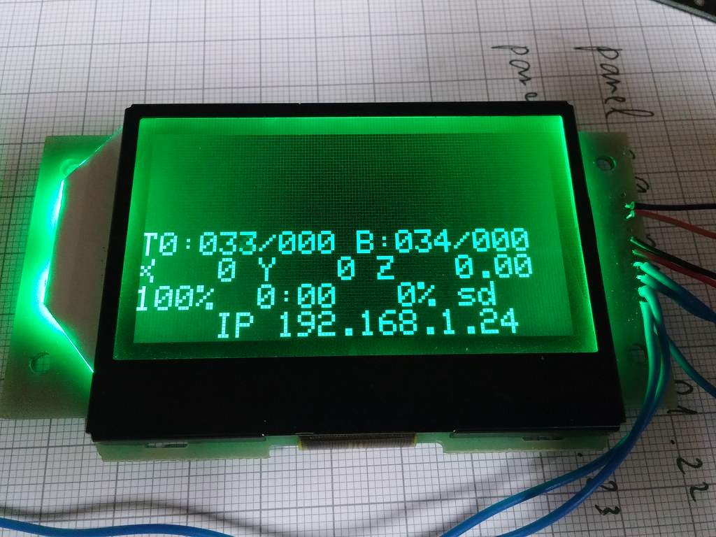
Some progress on the integration of this LCD display: it works! not perfectly, but now is readable.
I confirm that both /RST and A0 pins are needed in order to make the display work.
Both “viki2” and “st7565_glcd” driver works, but with the st7565_glcd everything is upside down.
The contrast need to be put at about 45 to have a clear view.
No pins need to be reversed, so my config code is the following:
# Panel
panel.enable                                 true             # set to true to enable the panel code
#panel.lcd                                   st7565_glcd     # set type of panel (upside down)
panel.lcd                                    viki2           # set type of panel
panel.a0_pin                                 1.23            # st7565 needs an a0
panel.rst_pin                                1.22            # st7565 needs an rst
panel.contrast                     45             # Adafruit Negative Panel Contrast
panel.encoder_a_pin                          3.25!^            # encoder pin
panel.encoder_b_pin                          3.26!^            # encoder pin
panel.spi_channel                           0                 # spi channel to use
panel.spi_cs_pin                            0.16              # spi chip select
Now my problem is quite strange and is the alignment of the text in the panel; it seems shifted some pixel to the left and some rows down respect some screenshot in the panel section of the website; which can be the problem? I miss some configuration about offset of the text? How can I correct it?
Some other update on my road to make a custom panel and, if possible, to play with some graphics to change the default menu, this is what i have in mind.
At the moment I’m stuck with the “offset” issue of the panel; I attached a rotary encoder so everything works (up - down and click), but as you can see from the main menu seems that the starting point of the display (pixel 0,0) is in some way moved a lot from the origin.
I think this is not a configuration issue, but some specific “error” between display library in smoothieware and my panel.
I want to try to fix it, creating a sort of custom library and changing it.
In particular, what function or part of the library can be responsible for this kind of offset?
Thank you Arthur, I will certainly take a look at that.
I already tested the “menu_offset” option but seems nothing had changed; I think that i need to go deeper also in the ST7565.cpp file.
I see that there are some variant (standard, viki2, miniviki2) of the ST7565 and probably the panel that I have has some sort of different managing of the internal display memory (pages etc…) I have less experience with gLCD displays, but if I remember well some alphanumeric displays have some issues regarding where you write if not properly initialized.
I think that i need to make a sort of third variant of the ST7565 constructor to properly initialize mine.
I’ll keep updated on progress
I’m return on this topic after some time.
I think that the problem of “shifted lines and rows” on my display is related to something in the initialization of the display:
Digging into ST7565.cpp file I found the initialization sequence array:
const unsigned char init_seq[] = {
        0x40,    //Display start line 0
        (unsigned char)(reversed ? 0xa0 : 0xa1), // ADC
        (unsigned char)(reversed ? 0xc8 : 0xc0), // COM select
        0xa6,    //Display normal
        0xa2,    //Set Bias 1/9 (Duty 1/65)
        0x2f,    //Booster, Regulator and Follower On
        0xf8,    //Set internal Booster to 4x
        0x00,    //WHAT ARE THESE 0x00 for?
        0x27,    //Contrast set
        0x81,
        this->contrast,    //contrast value
        0xac,    //No indicator
        0x00,    WHAT ARE THESE 0x00 for?
        0xaf,    //Display on
    };
a) first question is: what are used for the two 0x00 rows? only for timing purpose or include some init codes? I see that there are no comment on that.
b) I play with the first line: “0x40, //Display start line 0” that is correctly the initialization to 00000 line with code 010 (0x4); I try to change the position of the starting line and effectively the display respond moving the first row up or down when the display is initialized, but I’m not able to find the correct position. Moreover, the starting pixel seems some way shifted to the left of one or two column as you can see in the previously posted picture (check how the T and X are cut from the left border), but with this code I think I only be able to move the starting line; where the control for “starting column” is?
Thank you very much.
Hello, I retreive this quite old post, but I want to share some update on the LCD (now working) so it can be useful to other in the community that want to use the same setup.
LCD Adafruit Negative GLCD from Vatronix manufacturer
The problem with the “shifted screen” was due to two separate problems:
1.) the pagemapping of this specific display is somewhat different from “standard” ST7565, so the correct order of the pages are {4,5,6,7,0,1,2,3}
2.) the screen seems shifted to left by 1 pixel because the memory mapping starts from 0x01 and not 0x00.
Solution for 1.) in the file ST7565.cpp: implementation of ST7565::send_pic it is possible to modify like this:
WAS
void ST7565::send_pic(const unsigned char *data)
{
    for (int i = 0; i < LCDPAGES; i++) {
        set_xy(0, i);
        send_data(data + i * LCDWIDTH, LCDWIDTH);
    }
}
IS
void ST7565::send_pic(const unsigned char *data)
{
    int pagemap[] = {4,5,6,7,0,1,2,3}   //Remapping of pageorder
    for (int i = 0; i < LCDPAGES; i++) {
        set_xy(1, pagemap[i]);  //the column starts from 1 and the map scan uses the defined array
        send_data(data + i * LCDWIDTH, LCDWIDTH);
    }
}
solution for 2.) in the file ST7565.cpp: implementation of ST7565::set_xy modified to take into account of the “new” shifted clamp borders
 Try leaving it disconnected and see if it works …