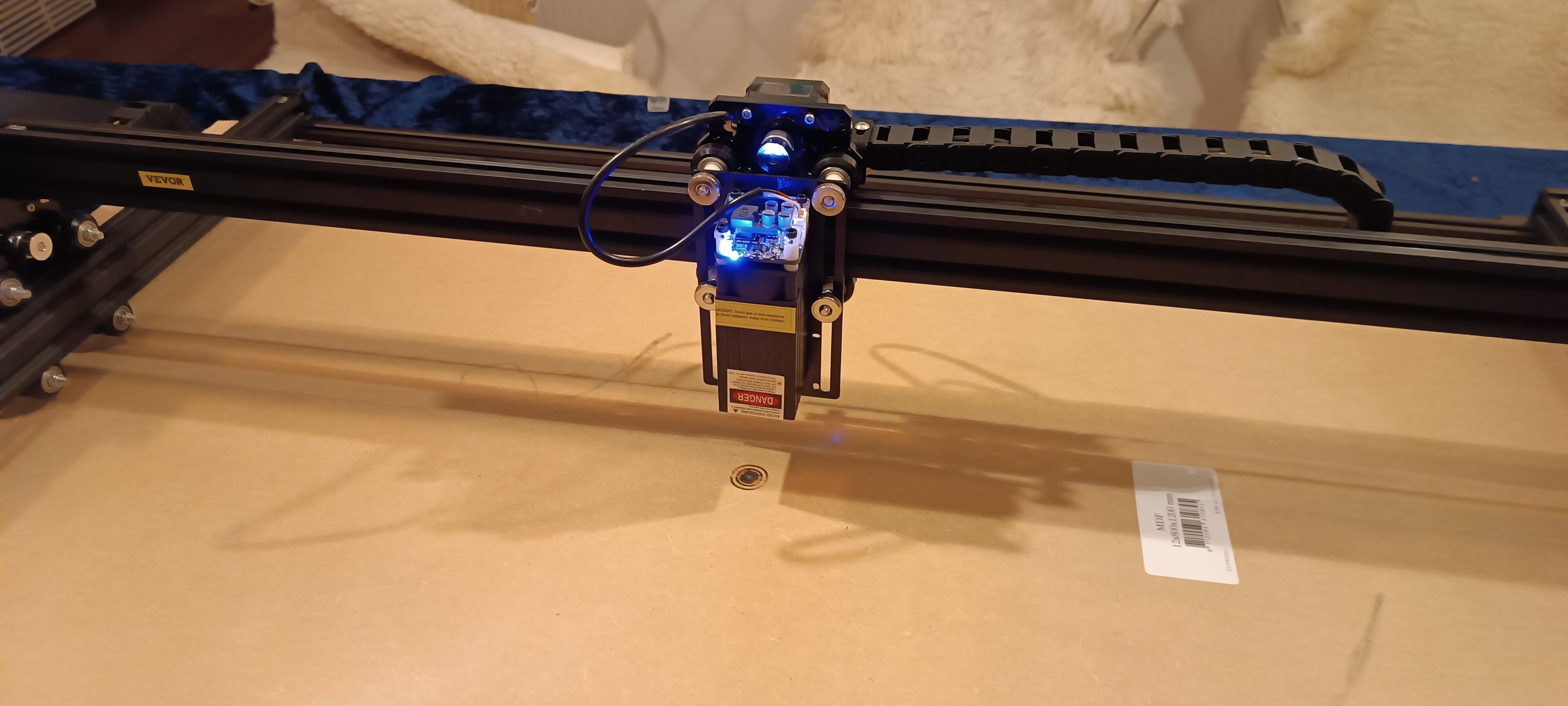
I have a L4681 Laser Engraving Machine from Vevor, and I’m using LaserGRBL. Now I would like to convert it into a pen plotter machine.
Since I have previously made a Polargraph, I have components I can use, such as a servo motor for the z-axis to lift the pen between the lines.
Now I’m facing the challenge that I’m not very knowledgeable about electronics.
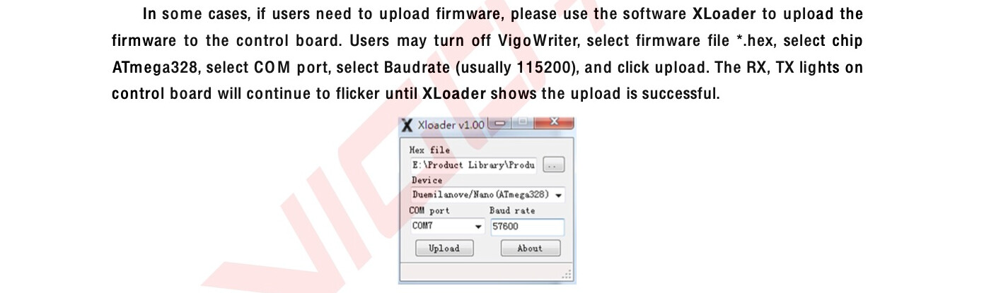
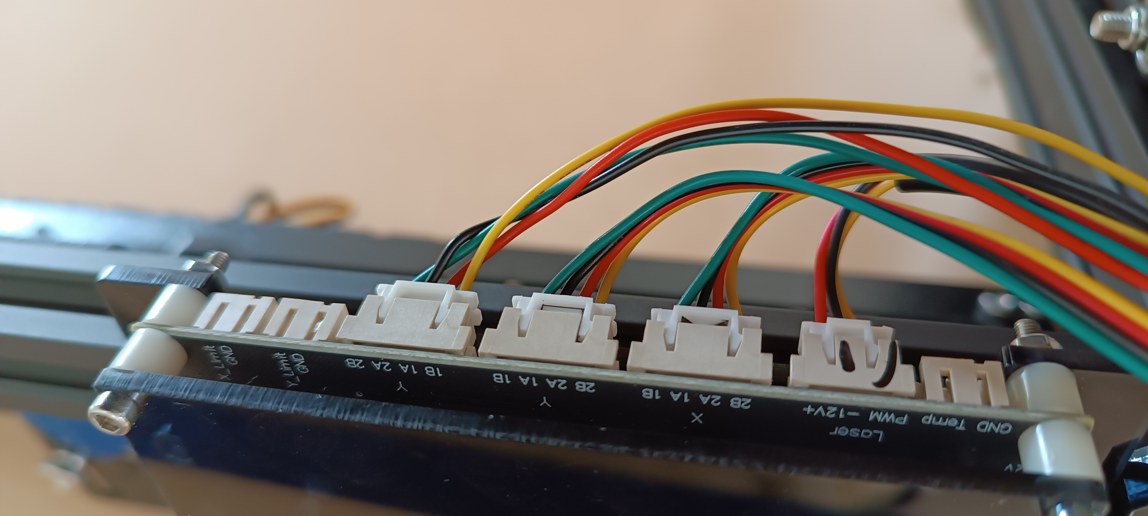
This machine has a built in VIGO-28 control board, which I can’t find any information about anywhere. I think it’s a modified version of a ATmega328 - its packaged with XLoader and a .hex file. I can find this on their website:
Alternatively, I have an Arduino Uno, a CNC shield, and the like, but then I would have to start from scratch with a new installation, and I like this board with built in wifi and a SD-card slot.
Hi Stine,
I think it should be possible to do this without modifying firmware if you use the existing (and already configured ;-)) laser PWM line to drive a solenoid/servo pen lifter.
I can see hree different ways to approach this;
The simplest uses a solenoid to pull the pen down in a sleeve and into contact (with a spring in between to relieve pressure). Match the solenoid voltage to the laser supply and use a mosfet to energise the solenoid depending on the pwm output.
If your controller already has a power mosfet for a Spindle on it (for CNC users) you can use that, and avoid any extra circuitry at all…
The goal is to map PWM 0% to ‘pen up’, and PWM 100% to pen down.
Or use a servo, this can also be a simple mechanism where the pen drops by gravity and the servo arm raises it up when not drawing.
In theory you then set the PWM frequency to match the servo frequency (often 20K) and then set the PWM minimum and maximum settings to be the correct ‘pulse duration’ for the servo control.
But this is done in firmware … eg you set the base PWM frequency, map the ‘minimum pwm’ and ‘maximum pwm’ in your firmware to the range used in PWM.
The point about servos is that they are ‘pulse width’ triggered, not ‘true’ PWM. You can use PWM, to generate the pulses but only over a small part of the full PWM range,
There is a whole bunch of discussion about this here: pwm to servo site:forum.arduino.cc
Still use a servo, but build a servo driver circuit that provides the correct pulses for the servo ‘on’ and ‘off’ depending on the laser PWM ‘high’ or ‘low’ status.
You wont have to mess with Firmware in this case. But it does involve some electronics work.
There are a lot of 555 based servo driver circuits out there, it’s a relatively simple design.
Finally PAY ATTENTION to voltage levels if you are driving a 5 or 12V servo from a 3.3v controller… Opto-Isolators are your friend…
Whatever gcode you generate should use only full on / full off values for the laser, avoid intermediate powers.