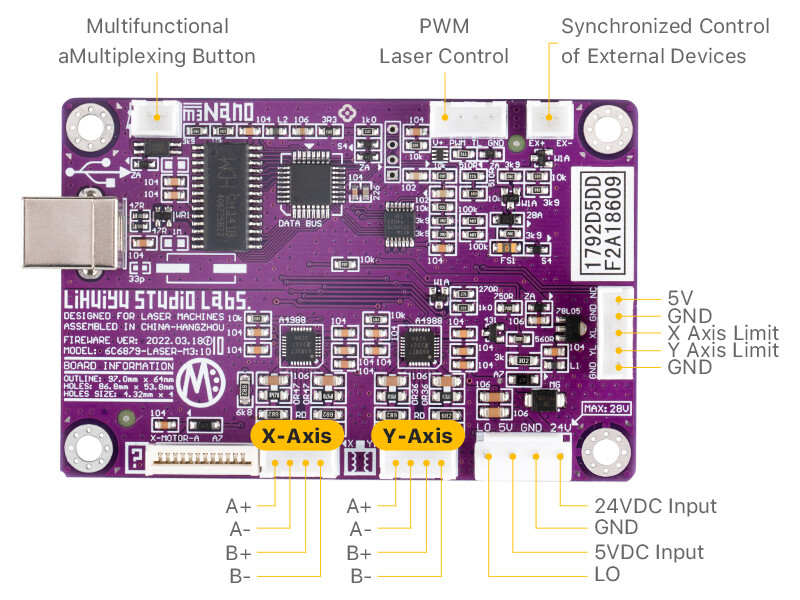
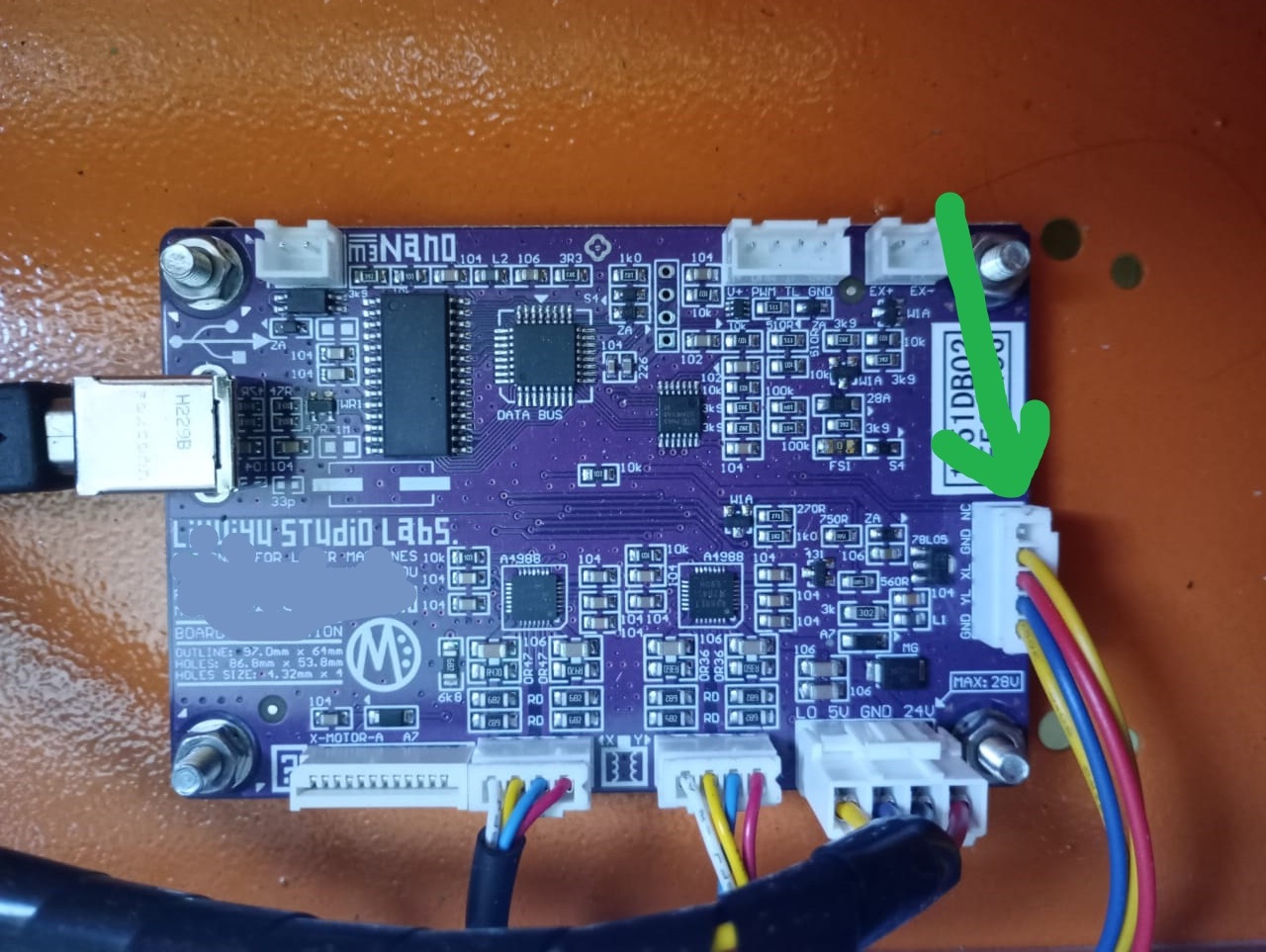
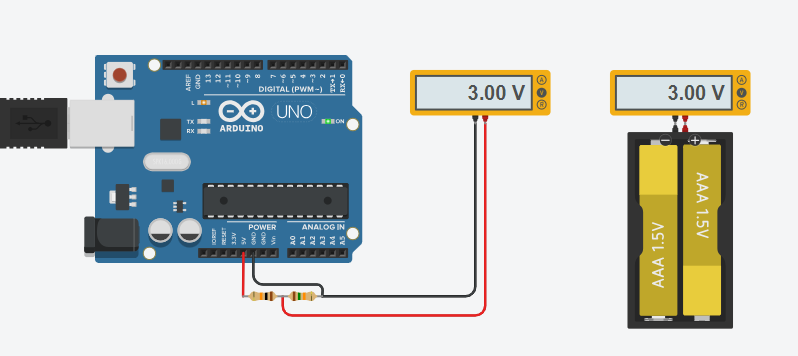
Hi, I have a k40 machine, it has a temperature sensor that uses two 1.5v batteries. I was thinking if it’s possible to get rid of the batteries and connect the temperature sensor display to the board. I noticed there’s a 5v free spot on one of the board outputs, I could connect a wire there to the display with a circuit made with resistors that reduces the voltage from 5v to 3v I found on youtube.
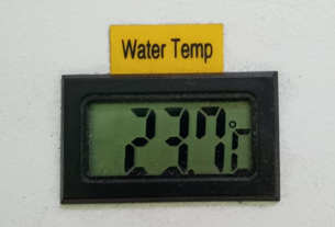
The temp sensor is taped to the outlet tube. The measured temperature is not very accurate. It’s much better to dunk the sensor into the reservoir.
At typical flow rates, the water coming out of the tube is at most 1-2°C warmer. Knowing the reservoir temp is all you really need.
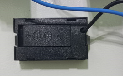
The two button cells in the thermometer module which came with my K40 are in parallel. It turns on with just one cell. So, it’s 1.5V.
Getting 5V from that particular pin is a bit difficult since you kinda need crimp stuff for that connector type. I’d get it from the power supply. You might be able to get 5V from the PWM header (V+). You could use a female Dupont wire there.
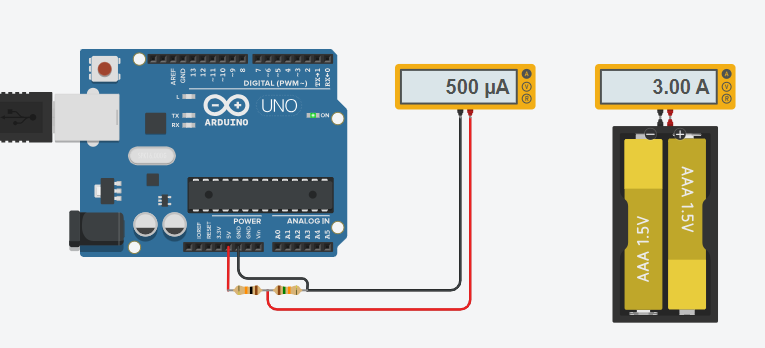
The proper way to do this would be a voltage regulator.
Anyhow, some quick googling suggests an LR44 cell has a capacity of 150 mAh. So, 300 mAh for two of them. One AAA cell got 1200 mAh (4x) and an AA cell about twice as much (8x). Either one would last for something like 8+ years.
Ah, so you’re really just wanting to POWER the temp sensor display from your K40 system. The title to the thread sounds like you want to connect a sensor to the controller board.
My approach would be to use a Multi-meter(DMM) in resistance/continuity mode to determine what voltage the display requires and to do that you look at the battery for their individual voltage and then you look at the 4 contacts in the battery compartment, make some measurements and see if:
1: The + of one battery is connected to the - of the other.
This indicates the batteries are in series/serial so you would need to supply 2X what one battery label says its voltage is.
2: See if the + of one battery is connected to the + of the other battery and if so you should see that the - of one is also connected to the - of the other battery.
This indicates the batteries are in parallel and you would want to supply only 1X what one battery label says its voltage is.
Then if there is that voltage available on your controller board connect it up and if not, find a $5 DC-DC converter online and connect that to the 5V on the board or if it supports 24V input voltage connect it to the 24V input to the controller(if you have an external 24V power supply). Otherwise, get a wall-wart withthe output you need and wire it to the AC power leading to your LPS.