Hi again.
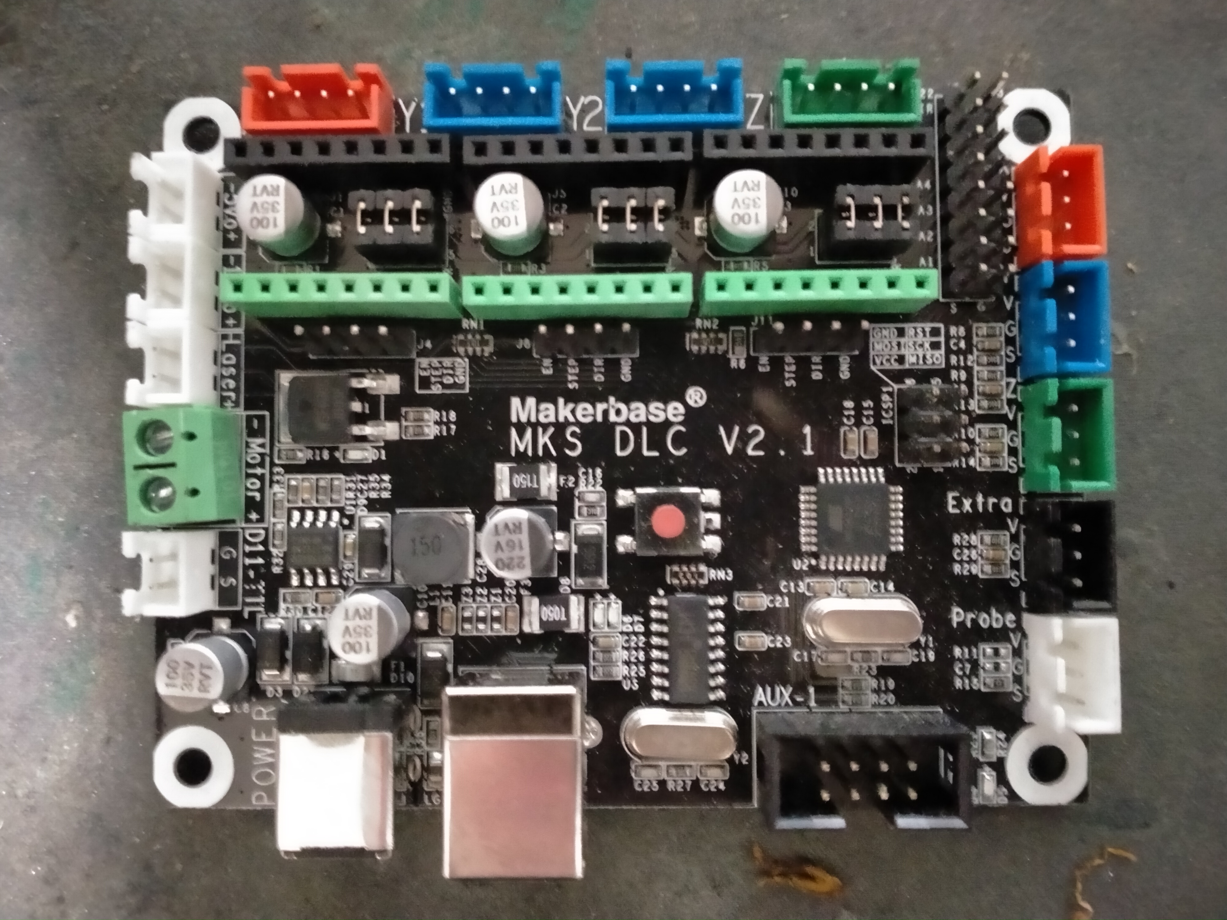
I recently purchased a Makerbase controller board (MKS DLC V2.1) and I’m now looking how best to use it.
It has a port for a laser (which, having tested with my meter is directly connected to the port next to it - for a CNC spindle motor - which makes sense).
The laser port is only a 2-pin affair, but the laser I have in mind is a 3-pin unit with the extra pin being PWM (5V). I had a similar problem when using an old Creality board and eventually found an answer in another forum (see my posting on making a cheap laser engraver). I wonder if anyone has solved this problem already, to save me trawling the web.
Basically where should I connect the PWM pin from the laser?
I’m pretty sure it should be to the S pin of D11 (TTL) but I’m not sure if that is 5V or 12V…I guess I’ll have to break-out the meter 
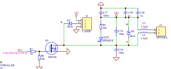
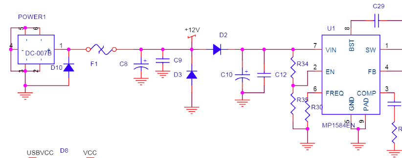
Here is the schematic for that board:
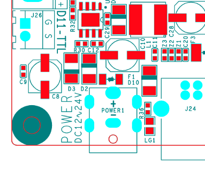
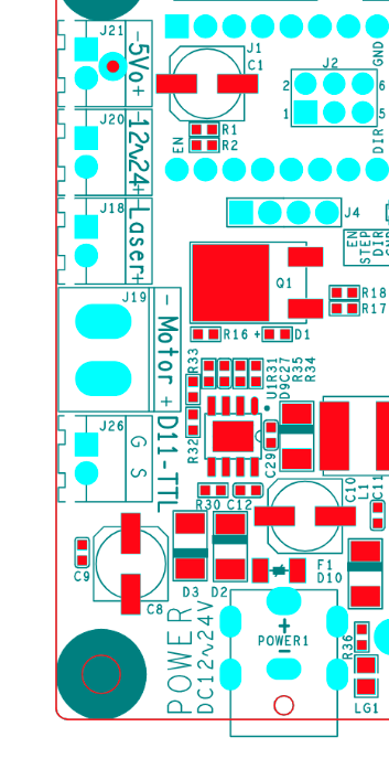
Although I see it on the board layout I could not find S on D11 on the schematic??? The board layout shows J26 as the S & G connection although the schematic does not label them as such?
On sheet 4 there are two LASER connections and a MOTOR connection:
- LASER J26-2: this is MOSI_LC, P3, D11 directly from the processor. I am pretty sure VCC on this board & processor is 5V but I did not check carefully. If you use this you have to check the source & sink specs on the Laser diode module and the processor I/O port (40ma?)(Atmel 328P).
- LASER: J18-1 this is an uncommitted (open-drain) Mosfet driven by MOSI_LC. Add a pullup to VCC (5V) and this should work to drive the PWM on the laser.
- MOTOR: J19-1 this is an uncommitted (open-drain) Mosfet driven by MOSI_LC. Add a pullup to VCC (5V) and this should work to drive the PWM on the laser.
All of these should work to drive the diode laser’s PWM assuming it’s expecting a TTL-like signal. My approach would be:
- I don’t like taking processor signals directly off-board. You could use an optocoupler to isolate MOSI_LC but that is more work than #2 & #3.
- I would try #2 or 3.
Careful, pin 2 on J18-19 is 12V so you have to pick up ground somewhere else. Pin 1 on the 12V FAN output, which is nearby, is ground. Alternately, you can pick up ground on various headers or at the power input connection, or on D11 pin 1.
Note: I am assuming the PWM that the laser module expects is a 0-5v or TTL compatible signal.
J26-2 is inverted, relative to J18-1 and J19-1.

True that!
Which I guess is a problem if the running firmware cannot (Grbl?) invert the PWM signal.
@donkjr is right. Grbl cannot invert the PWM signal. So you have to use J26 pin 2 (or you get inverted laser power). The PWM input of the laser driver should be signal level and not need too much current.
Be careful here. This is the output of my Woodpecker grbl board
I know on that board that the laser fires when the PWM signal goes high. That would indicate you should probably not use J26-2.
Never had to invert the PWM signal, but did bump into a number of people that have apparently done that.
“the simples way is to change the pwm value from x to 256-x that will invert
the pulse.” from github forum on the Arduino grbl code.
There are also other ways, as with most microcontrollers.
![]()
Attention: You can’t just invert the PWM signal by changing the grbl source in one place to use 256-x. There are features in grbl that deactivate pwm below a minimal value, or adaptive laser power M4 which would not work with this hack!
Your schematics shows a mosfet which inverts the D11 signal by using the drain to pull the laser pin 2 to gnd when D11 is high! This is not like TTL diode drivers work. They need a +5V signal on the TTL line to activate the laser. Your logic is used for most CO2 LPS.
Just picked up that from one of the people changing it that it is probably possible to invert it. Anytime you change source you pay your money and takes your chances.
How about just setting COM0A1 and COM0A0 to 1? Assuming I have the right registers.
That shouldn’t effect anything else… yes/no?
You must be assuming the output of the micro is high to be on. Look back at the schematic, invert your logic and take into consideration the zener.
Wow - this is a little more involved than I realised - very glad I checked here first
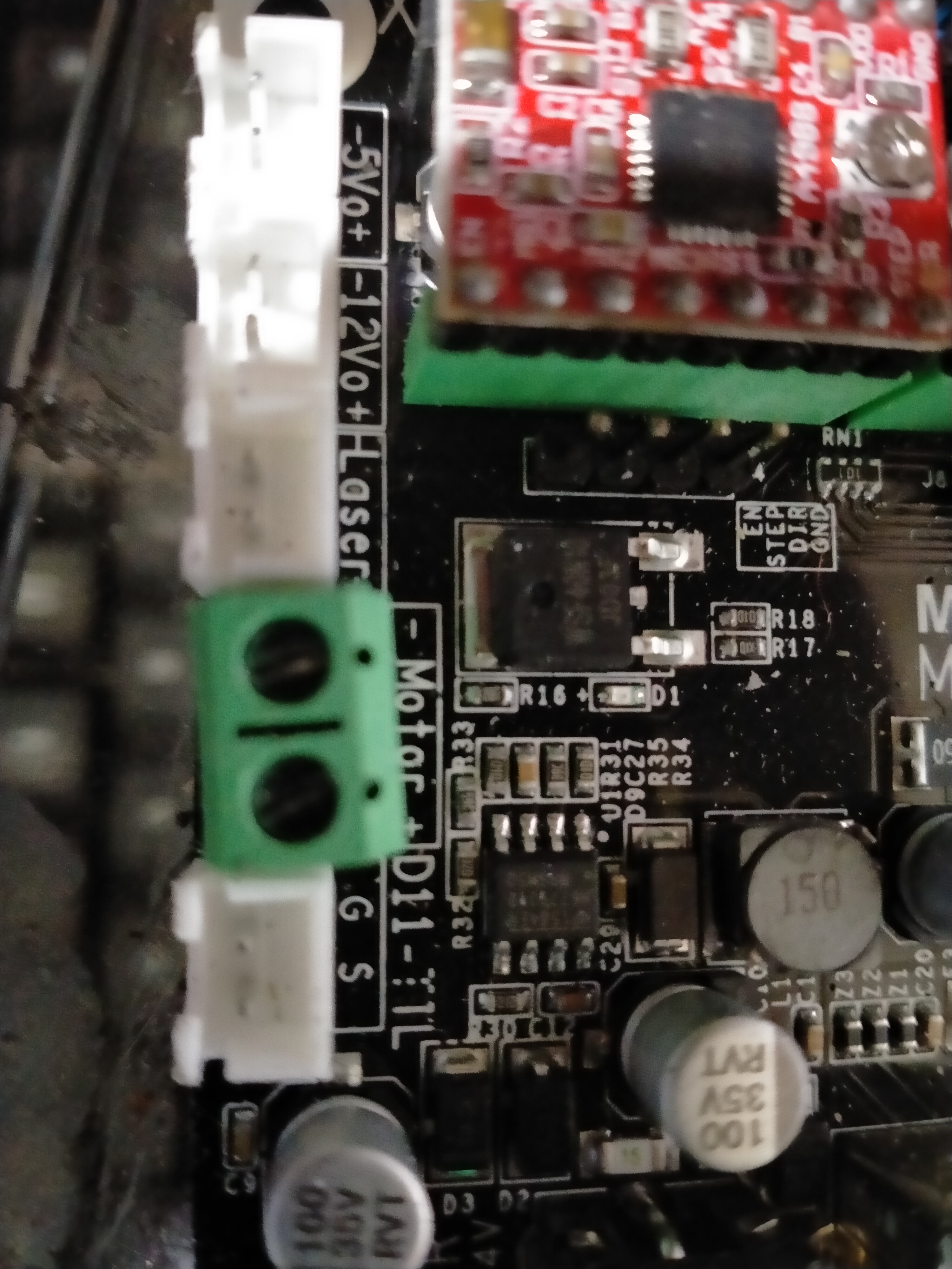
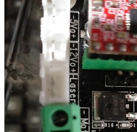
I’ve zoomed into the part of the board in question. You can now see the laser and motor connectors, and below is D11-TTL with a ground and signal connection. Above the laser connector are 5v and 12v connectors.
My assumption was that I could connect the +/- wires from the laser to the laser connector and the pwm wire to the S connector of D11, but if I’m reading correctly (dumbo alert - to call my knowledge of electronics ‘basic’ is probably overstating it) then this is not the way to go?
If this is the controllers ttl PWM output, then that’s probably true.
If you have 100 watt laser you can’t power it off the board. Doubt you have that large of one, but you need to be able to supply it’s input power requirements. Some can be supplied by the board, but it will limit how powerful of a laser you can run. Two of the three of mine have external power supplies.
The PWM is connected to the Laser PWM, as in the schematic I posted. Power was supplied from another power supply. 500mw laser that came with it, has two wires and used the Mosfet to switch power for control.
![]()
No, the laser is a diode chinese jobby with nominal 40W total power (probably giving somewhere around 10W laser power).
I think we have overcomplicated the answer with too much choice that did not result in an answer to your question.
Hope this post does not make it more complicated …
You are trying to drive your laser diode module with the MKS DLC V2.1 controller.
Your Laser diode module has these inputs:
- 12V [current needed?]
- Ground
- PWM [this is presumably TTL compatible where: 0-.8v is low (laser off) and >2V is high (laser on)]
PWM output on MKS DLC V2.1 board:
J26-2: [also labeled as D11-S] should be a non-inverted PWM signal that is TTL compatible.
J26-1: [D11-G] is ground
Power output on MKS DLC V2.1 board:
The 12V power from the MKS DLC does not likely have the capacity to drive the laser.
UPDATE: not entirely true: see below
I would employ an external 12V supply of 5A capacity.
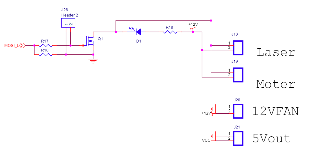
This should work:
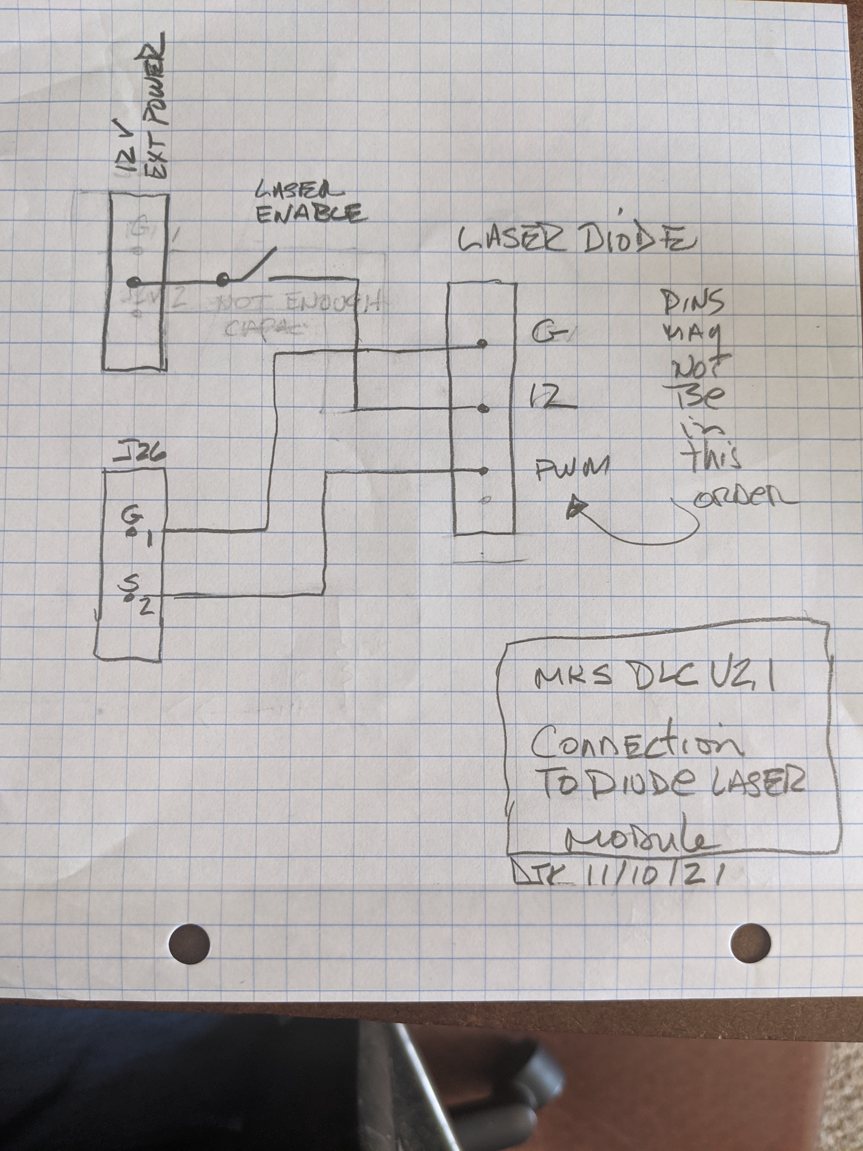
In this schema, the laser’s DC power is on as soon as the controller is on [not good]. I would add a “laser enable” function in series with the 12V line to insure the laser does not fire accidentally. This can be as simple as a switch.
UPDATE: using the 12 or 24vdc connector.
It looks like the 12/24 volt connector J20 is an output of whatever the DC input is. A DC-007b is a DC power jack. The internal power bus is labeled 12V yet the input power connector on board is labeled 12 or 24V, that is not confusing …!
This means that:
- If you are running 12V to the board J20 will have 12V on it. Note1.
- If you are running 24V it will have 24V on it.
Note 1: If the capacity of the board’s supply is in the order of 12V@5A you could use that connector for the laser diode. Using this has the advantage of an onboard fuse and one less supply but the disadvantage of not being able to power the steppers @ 24V.
If you are running the board from 24V you cannot use that connector.
If you decide to use J20 verify its voltage and ground levels before connecting it to the diode.
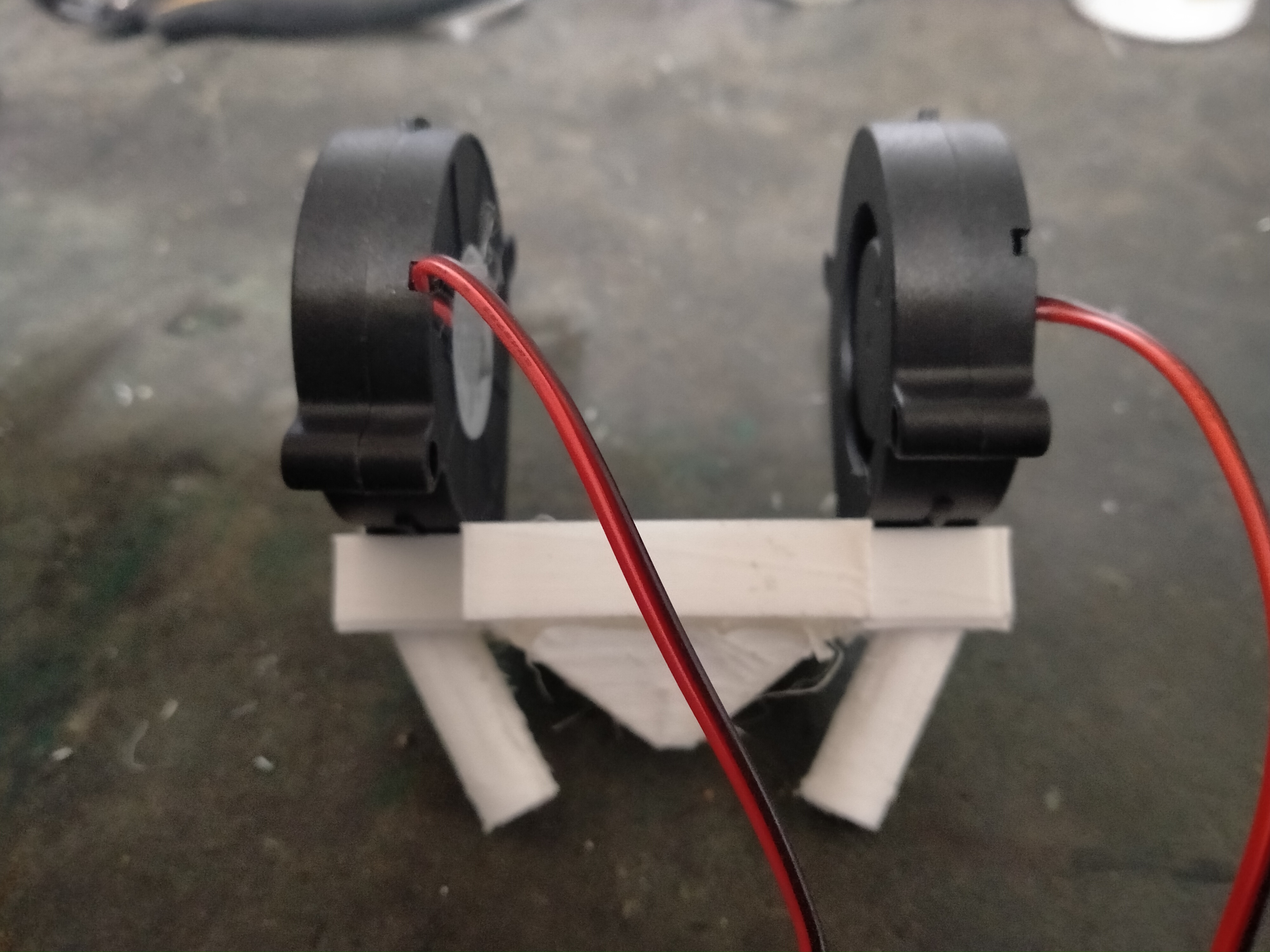
OK…I get that. I’m actually using a 12V PSU to power the board and it has plenty of spare oomph (technical term ). So I’ll split the 3-way wire from the laser, take the pwm to J26-2 and take the other two to the PSU 12V output via a switch. I’ve actually already got a switch operating from the PSU to control my homemade air assist (pic below), so I can just tie into that for the laser power.
PS - is J20 the two-pin connector just above the ‘laser’ connector, labelled 12Vo? I presume so.
Just to make sure you know. If you are using 12v at enought capacity to the board you can use J20 for the laser’s power.
Thanks Don,
if J20 is the 12V 2 pin connector (labelled 12Vo on the board) then no problem. The PSU is rated 10A if my memory serves…it’s fairly chunky.
PS - just re-read your posting properly and J20 is indeed the one I thought. If that is OK to power the laser then would not the ‘laser’ connector also be OK?
Ahh…I think I can answer my own question. J20 is tied directly to the power input whereas the laser port isn’t.
Yup, the LASER is a control port not a power connection.
More confusion.
In the layout docs that connector is labeled 12 [strange symbol] 24V
on your its:
Don, I suspicious that there is a tactical issue with this.
Expecting to be able to run 10 amps through circuit board size traces, is asking for an issue. I’ve done circuit boards and the trace width becomes very large at even low currents, such as 5 amps.
I went to the digikey trace width calculator.
At 5 amps, 6mm (about 1/4") long, including a 5 C increase in temperature, on 1 oz pcb. The trace needs to be almost 11mm wide to carry that amount of current.
IMHO: I think that some part of that board is going to be the fusible link.
I’ve always run mine with a separate supply.
Well, since doing that (running the laser supply from the PSU directly) is not a problem then that’s what I’ll do.
Thinking about the issue of the laser coming on at power-up…isn’t it the case that pwm=0v means the laser will be off (yes, the fan will spin up, but it won’t actually lase until pwm>0v) ?
I would not expect it to be 10 amps? ![]()
I would guess more like 2- 4 amps.
There is also a fuse on that board.
To be sure one would have to inspect the land areas from input to the connector.
In systems designed for laser safety, I do not trust my eyes to software and electronics. Experience has taught me not to trust software and hardware design where I cannot see code and schematics for myself.
I would not assume the PWM asserts to 0 before the 12V comes up. Although it should, I would not trust the controller to hold PWM at 0 during POR.
Lack of manual control of the laser’s power also assumes that the driver software will never activate nor leave a job running without you asserting or knowing it has been left on.
I don’t like [and neither do laser safety stds] conditions where the laser can be on without you knowing or deliberately enabling it.
I have already seen one case where VigoWorks left the laser on when it crashed.
Also when enabled there should be a clear indication that the system is UNSAFE.
I plan to have a Laser Enable Switch, interlocks, and flashing strobe light added to my system that is in the 12V circuit. In addition, the user will be optically shielded from light exposure.