Can Grbl-LPC set the power via IN and fire via L?

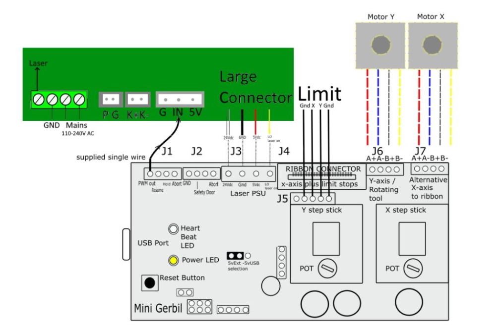
Is there a way to do the usual thing where power is set with a 20+ kHz PWM signal on IN and the laser is fired by pulling L to ground?

Bonus question: Is there a way to add pause (feed hold) and resume (cycle start) buttons?


In case anyone cares, here are the reasons why I’m not interested in the L-only PWM hack:

Setting IN to a fixed voltage and PWM on L does not look like it’s the way to do it. Controllers which support RF and DC tubes (e.g. Ruida RDC6442 G/S) use one pin for RF tubes and two pins for DC tubes. Why would they bother with another pin and a few extra components if this would be completely unnecessary? As far as I can tell, no controller you can find in Chinese or “Western” machines uses only one pin.

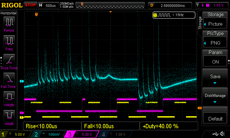
That one L PWM frequency works better for cutting and another works better for engraving also suggests that this isn’t quite right. You either lose power or fine-grained control. You don’t have this problem with two pins.

The wiring diagrams and pinouts from the power supply manufacturers also tell you how these two pins are supposed to be used. An L-only alternative isn’t mentioned anywhere. (Please correct me if I’m wrong.)

There doesn’t seem to be any advantage in using this L-only PWM hack. It seems to kind-of work, but not as good as using two pins. It isn’t equivalent or better. Therefore, I have no interest in using it.

wouldn’t this depend on what hardware you are using to control the voltage on IN since most boards do not have a Digital to Analog(D2A) converter to generate a variable voltage and that circuit would have to be fast enough to handle 254DPI at 300mm/s.

Do you have any links to sections of LPS docs which point out other ways to control power level and ON/OFF control differently than a fixed max voltage on IN and PWM on L?

BTW, with LinuxCNC I’m able to switch PWM base frequency on the fly. CAM tools don’t provide this option so the gcode would have to be edited or post processed to do this.

PWM on L and DC voltage on IN is not a hack, it’s the way all K40 Lasers with analog control work from the factory!

This makes absolute sens if you trace the internal logic of the K40 LPS.

I made alot of tests and don’t see ANY advantage of having PWM value and enable saparated in grbl, because grbl in laser mode does PWM 0 when laser is disabled.

By the way: The different frequency response has nothing to do with the used pin on the LPS, it 's a mix of material properties (time to burn) and over/undershoot of the LPS.

1 Like

K40s with analog or digital control panel cannot control the power via software.

With the analog control panel, you can adjust the voltage going to IN.

With the digital control panel, you essentially do the same thing. The frequency of the PWM signal going to IN is so high that it might as well be an analog voltage. (Same deal with Ruida controllers etc. This is how they adjust the power for DC/glass tubes.)

The M2 Nano controller then pulls L to ground when it wants to fire the laser.

When you raster engrave, it draws longer or shorter lines. What you get on L is a 1:1 representation of the pixel data. It’s not PWM. It’s not about adjusting the average power. It either fires for this pixel or it doesn’t.

With Grbl-LPC, IN is set to a fixed value of 5 V (or whatever you want to be the maximum) and then a PWM signal on L is used to fire the laser and its duty cycle is used to adjust the power. L is pulled to ground several times when it draws a single pixel.

Using a single PWM signal to adjust the power and to fire the laser (and to provide a pre-ionizing tickle) is how it’s done with RF/metal tubes. However, I do have a DC/glass tube which has much higher response times. You can’t pulse it like an RF/metal tube.

Of course I also don’t have software which adjusts the frequency to match the resolution in order to get the same amount of pulses for every pixel. Trotec’s JobControl does this kind of thing when you set the PPI to auto, for example.

Anyhow, I got a DC/glass tube and I want to talk to its power supply like a Ruida/Trocen/etc controller would. Or Mini Gerbil, for that matter. I want to do the usual thing and get the usual behavior.

When you tell the power supply to fire, it will try to ramp up the power to the chosen power level as quickly as possible. In the spec sheet, you can see things like >90% of the requested power in X time. Better power supplies may do a better job and ramp up and down a bit quicker.

When you ask for 100% power, but switch it on/off very quickly with a 50% PWM signal, getting more output that 8 mA isn’t really overshooting. You asked for 100%, but it couldn’t pulse that quickly. It’s undershooting in a sluggish manner.

Well, I’m not really interested in this new can of worms. I want the old can of worms I’m familiar with.

There is a major difference between diy firmwares (like smoothieware, marlin, grbl) and commercial machines (like Ruida, Trotec…).

Commercial machines use PPi rastering with fixed laser power for grayscale engraving.
The diy firmwares try to modulate the laser power for each pixel.

But I see, you are not interested in my experience and prefer your theory, so I suggest to go with a commercial controller, and I’m out…

Smoothieware, Grbl_ESP32, and Mini Gerbil’s Grbl fork can/do use two pins.

I’m not interested in these experiments. Using one pin less isn’t a major advantage. There are quite a lot of wires. One wire less doesn’t really affect anything. I would like to do the usual thing with the known/specified/as-designed behavior.

For what it’s worth, I do regret outlining why I’m not interested in using a single pin. I kind of anticipated that I’d get defensive replies, but I also really didn’t want to hear how using one pin works almost as good etc. I wanted to shoot that down. Looks like that didn’t work either. I really only wanted to know if there is a way to make it work like 99% of the other controllers.

Yea, I’ll probably do that.

Thanks for your time. I should have kept this a lot shorter.

This grbl board is connected to the lps the same way as the Ruida.

The designated use of the IN for an lps is to control power. If you put a analog or digital signal there it is eventually the pwm that actually turns the tube on and off to produce an apparent difference in power.

However if the laser is not enabled to fire, nothing happens. When L on the lps is pulled low that enables the laser and it lases at whatever in going into the IN input. You are in effect turning on and off the pwm set at IN.

@cprezzi I don’t know what a ‘PPi rastering’ is. Could you advise?
Actually I’d call the pot on the IN terminal a hack for the K40. Yes it’s standard, but it’s one less control line they have to deal with. They remove the automated power control and put a pot there… it’s cheap.


Most grbl boards do not have an L to enable the laser. Most led lasers are controlled by the pwm… maybe a natural move. Also active L is low and active pwm is high. Some lps have an H, an inverted L input.

It’s not required to be a high frequency. Here is a screenshot of mine drawing a line of dithers with a 1mS period for the pwm (1kHz). Normally the Ruida has a 50uS period (20kHz). You can change it in the controller. Even the Arduino has a 1kHz pwm.

Blue is voltage across the mA meter. Purple is L (L-On1 Ruida) and is the trigger. The yellow is the pwm at 40% power.

Probably not what you expected… had me scratching my head a while…

The pot on a K40 doesn’t really control how much current your tube gets. The tube will draw whatever the lps can deliver… you have to adjust the lps to limit tube current. If you use 50% power, that means you tube lases at 100% power for 50% of the time…

:smiley_cat:

Hi,

I am pretty new to laser stuff and new as well on this forum!
However I have already “touched” lasers (an old 25W CO2 Trotec which is almost dead today).
This is the reason why I try to refurbish this Trotec CNC into a “new” DIY 40W CO2 laser.
I had been given a CO2 40W tube and a cheap HV power supply that I am trying to “understand”.

So far I discovered that the D± and L signal are in serie. So it seems to me that these signal are “logical ones” and basically only perform the “enable” of the laser when all this chain is grounded (via an opto).

So I came also to the conclusion to use the IN signal as intended to modulate the laser beam via PWM.

This should be simple but my DIY laser controller will use an ESP32 and fluidNC firmware to control the steppers and the laser.
This MCU is 3.3V powered. The IN PWM should be a 5V one. So I will probably need some N mosfet to match the 3.3V PWM with the 5V one of the IN signal.

In conclusion using the IN signal as PWM will be more “complex” than using a digital PWM on pin L to “chop” the enable of the laser.
However I will probably stay on the IN PWM approach (one added mosfet on my board).

Apart from this hardware consideration has anybody tried to apply digital PWM on the IN pin ? Is there a frequency limitation on this IN input (not to damage the electronics or the tube itself) ?

Thanks for your help
JP

This is a configuration that is often used. As you have discovered it requires that attention is paid to how it is driven.
There isn’t a limit at the PWM frequencies that these machines are normally run at.

Note that when driving the “IN”:

  • It is not optically isolated like the L pin.
  • You loose the ability to externally adjust power as the laser wears out.

For DC/glass tubes, DSP controllers default to 20 kHz.

My DSP controller also defaults to 20 kHz and I haven’t changed that value.

thanks for this info.
20 kHz is easily achievable with ESP32 MCU.

The placard limits are usually a response time of <=1ms to reach 90% of the placarded voltage.

If your lps is doing this, then the fastest you can toggle the lps is 1kHz

:smile_cat: