Can anyone with a set of digital vernier callipers do me a favour & measure what is the precise width of the standard K40 laser head. I measured (with a tape/ruler) that it is 26mm, but it’s not quite correct. The friction fit is extremely tight on my printed air-assist nozzle, so I assume it’s fractionally larger than 26mm.
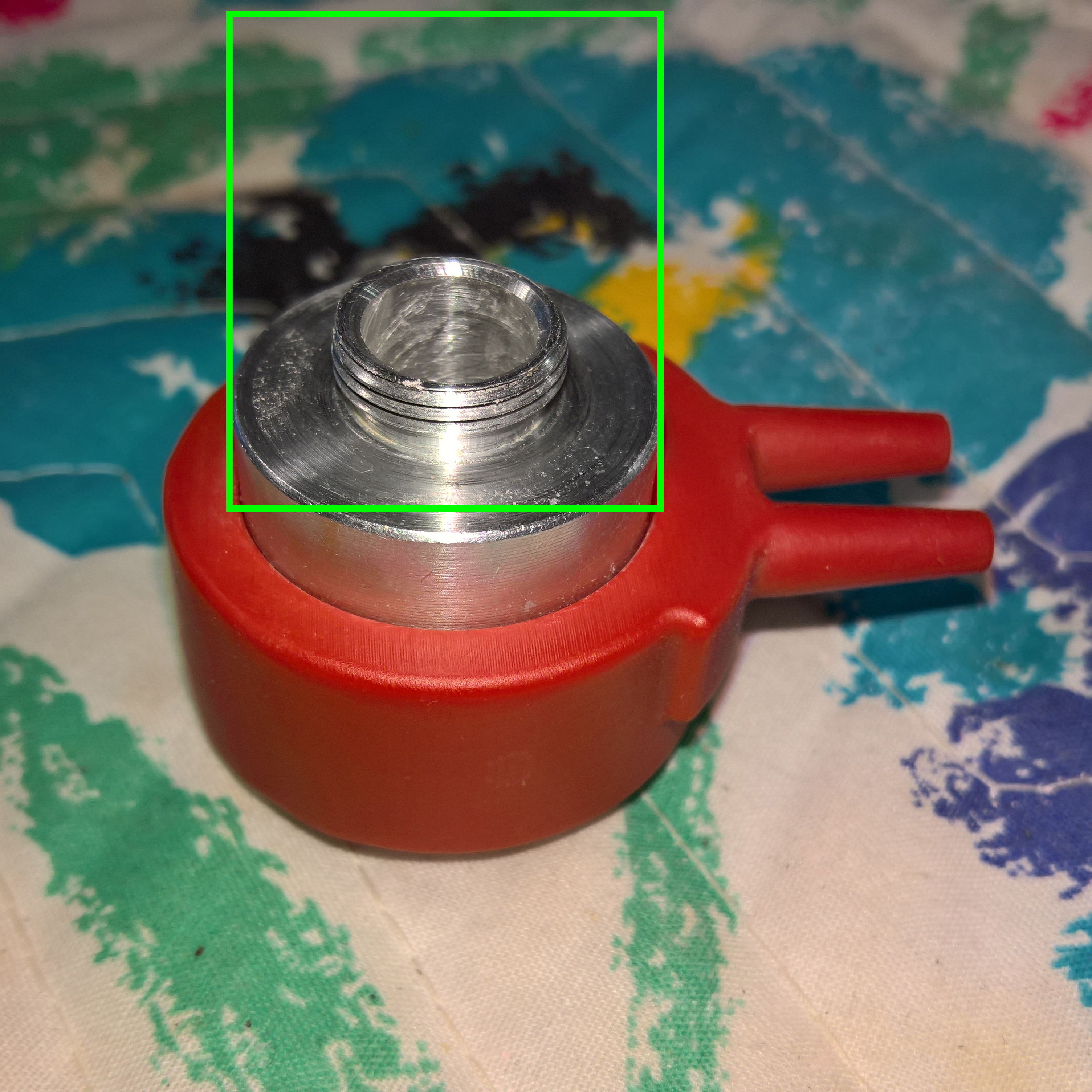
Also, I’ve realised that once the laser lens mount is in the nozzle, there is no method to get it out. Can’t push it from the bottom as there is nothing to push on except the lens. Any suggestions for v1.05 to make it easily removable? Or different methods to hold it in place? I’ve been having to remove it via pliers which can’t be good in the long run every time I need to clean lens.
I will measure mine in morning,the focal lens should not need cleaning with your design as any smoke is keept away by air and the air is not blowing on the lens so it should not get dirty
enlarge the inner diameter, and hold/tight it with a side screw (prisoner nut, if you print in abs, put a drop of acetone into nut hole, acetone will melt the abs locking the nut into place)
@Phillip_Conroy
Thanks for that. You’re probably right about the focal lens “should not” need cleaning with the design, however what should happen is not always the case where things I am doing are concerned lol.
@StephaneBUISSON Unfortunately due to the nature of the model, the outer walls are actually hollow, allowing the air to flow through there & meaning I would need to include a specific hole for a grub-screw or the likes. I’ve actually figured it out. Leave the bottom portion tight as it is & enlarge the inner diameter for the middle component of the lens mount assembly. That way the bottom part can stay in place forever (don’t need to take it out as per se) & just remove the middle component in order to get to the lens. It only needs to be 0.5mm larger for that section, so not a huge amount. On this particular print I’ve achieved this with some light sanding by hand.
@StephaneBUISSON This is a resin print, not PLA or ABS, although I have no idea what is in the chemical makeup of this resin. Might be worth checking with the guy who printed it for an MSDS. Thanks for the foil suggestion. If it turns out to work as well as intended I will look into getting them 3D printed using SLS & some form of metal (provided it is cost viable).
Thanks @Tony_Sobczak & @Scott_Marshall . Seems if they are not precisely the same for each one then something else would need to be done to standardise the nozzle to fit them. Since it seems from the difference in your results that there is a possibility of variations, I’d love to see results from more people to see what the +/- range is.
Not surprising there is less than repeatable results there. Typical machine work on this sort of thing is rough to be kind. They only change out cutters when they won’t cut anymore.
A set screw like Stephane suggests, or design in an o-ring groove for a snug fit on the generally largest expected may be adequate. I’m guessing they were shooting for 1.000" (25.4mm) - probably a copy of a US made part. As the cutter in a lathe/screw machine wears, the part grows.
If you want to go mass production, you may have to either state “hand fitting required” or go large with an o-ring groove and include 2 or 3 size o-rings and possibly a set screw. Should someone have a very small one a fallback would be RTV or a few turns of electrical tape (PVC).
It’s a ‘challenge’ designing for the old blue box… I’ve been working on my “Mod” kits for a few months, and have had to make a lot of changes to accommodate inconsistent spacing on the panel mounting studs for instance. These boxes are hand built and pretty “rough” if you really look at them.
I was hoping to provide a “bolt together” kit, but I’m going to have to instruct the installer to drill the new acrylic panel themselves (as you probably know drilling acrylic can be touchy for inexperienced builders) If they crack it, they’ll have to order a new one and change all the pre-mounted parts over. Then drill it (ouch) That’s not the kind of "User friendly I’m shooting for. I’m going to offer beta testers a discount to work out these issues. I was hoping to sell a “drop -in” easy kit, but it may have to be a “some fabrication required” Kit.
Don’t let this little challenge stop you, I think you have a viable product coming together.
@Scott_Marshall I think with your panel kit, you could create the acrylic with holes already in it & make the end user drill the lid of the machine instead. Less prone to cracking when it’s metal. I’m definitely interested in yours, especially if it comes as a kit that is mostly plug & play & just have to drill some holes in the machine for the panel. I was considering an aluminium panel for mine, but that would require CNC to get to the right shape/size/dimensions/holes/etc.
You’re probably right that they were designing for 25.4mm. I will have to give some extra thought to this as an end product, as if I get them done as a product, I’d like to get them made from metal. This will be less workable for the end user. Another option, since I intend to do from metal, is to have the entire lens mount section built into the model & then from there the rest of the lens mount middle & upper components can screw in via the existing thread. But at this stage I’m a bit unsure as to how they would machine or cast a piece that has hollow components like this model.
@Scott_Marshall Instead of drilling holes in the panel, can you just undersize the panels so the come close to (but not over) the studs and provide the users with fender washers that are fastened onto the studs and clamp onto the panel edges? Also, the panels are acrylic, so presumably the purchaser can also use their k40 to make the new holes prior to upgrading?
@Vince_Lee
Good thought Vince, I was concerned they would crack it trying to enlarge the holes. I hadn’t considered just suggesting the use of the laser if they don’t fit. I’ve already moved to fender washers, but you’re limited as to how big you can go by the inside edge.
Thanks for the tip. This is a lot of work, getting this kit deal together, I appreciate the help.
Scott
@Scott_Marshall perhaps if the distance from the posts to the opening doesn’t vary too much you can also laser cut slots instead of holes so the lateral position of the posts doesn’t really matter as much. It is great you are doing this. I had considered packaging my switcher board with parts as a kit myself and decided I didn’t want to commit to so much work. Let me know if I can help tho.