Building the first Electro-Mechanical Pedal Steel Guitar

Good idea… Would one board per 2 strings/motors make sense? It fits well with the motor control board layout.

so all the wiring from a daughter board to the main board could go over a single serial connection? Easier from a wiring perspective for sure…

I will… my understanding was that for my application a PID motor would work better than a stepper, but regardless, it will be helpful to look at how the serial protocol works.

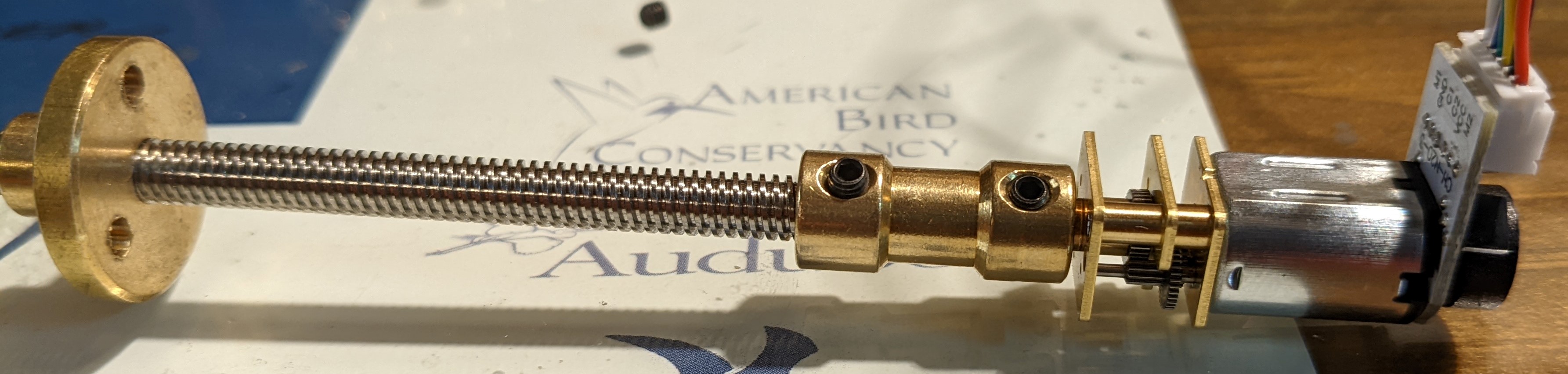
Edit: looks like he is using it as a servo after all… and that is the exact setup of my motor, except I didn’t have to add my own encoder. I like how he fit the control board in the same case with the motor. very compact… Reading about ‘backlash’ in the comments, I’m not sure I understand what that is exactly… I’ll have to read up on that. Does PID account for that?

reading this: XMoto DC as Servomotor | Details | Hackaday.io I’m wondering if this is not the same motor I have after all. It looks the same, but this is a ‘high power’ version, probably not available with a built-in encoder… this one will take 1.6A, and IIRC the one I ordered takes 500ma. Presumably, if the one I got doesn’t have enough power, I can go this route. This post is only 4 days old, so I’ll be following with interest!

If this solution doesn’t have the torque needed, I’ll probably be looking at a worm gear motor like that. 8 of those would take up a lot of space, though, so I’m hoping the smaller motor works. And the rpms are pretty low for my application, although some of them may get close enough.

Totally depends on the number of pins on the controller you use.

You’ll need one SPI channel per daughterboard. I²C you can have more on one bus but it’s slower. SPI is simpler and it’s what I’d use.

I’m pretty sure that the motor control daughterboards, even with slow CPUs, will not run out of compute power even if they are controlling lots of strings. I’d use as few daughterboards as I could get away with.

The HaD post was about something like what you are doing (though not as small) but I was linking to a library mentioned in a comment. That library implements both PID control and trapezoidal motion planning. I haven’t read the source code but if I understand correctly, it would probably be relatively easy to modify it so that instead of using STEP/DIR lines, you just send it motion commands over an SPI connection. It would be a starting point, not something you would use as-is, was at least the idea I had…

First read up from Wikipedia on what backlash is in engineering:

You don’t really have to worry about backlash at all because your mechanism is always under tension in one direction. This means that your gear train (if you have one) is always being tensioned in one direction, and the play between the gears never… comes into play!

PID is for movement management based on a sensor input for where you are and knowing where you want to go… Watch the video I linked to way back in comment 16 a few weeks ago to understand PID — it’s the best thing I’ve found yet for understanding what PID does for you. :smiling_face:

1 Like

okay, that makes sense.

Reading up here:

Looks like his motor is more similar to mine than I thought. Looks to be better built, but at 12v the amperage is cut in half. And the figures for torque on higher rpm gearings look similar to mine. But building the daughter-board right on to the motor does make a lot of sense from a physical layout perspective.

From what I can tell, it’s very much what I’m doing, at least from a hardware standpoint, right? and that motor is only 2mm wider than mine… but I will look at the library as well.

2 Likes

I didn’t realize it was so close to what you were doing in size. Cool!

Boy, a ton of info and links here: dcservo/README.md at master · misan/dcservo · GitHub
never mind the actual code.

Thanks! I’ll be studying in the library for a while now…

3 Likes

Wow, my google-fu is failing me as I looked and looked before finding something close and then mashing into my own version: This is what I’d posted about in Nov '21 and now realize I had not shown the motors I’ve been using or else @donkjr would have been made aware of them long ago. Use DC motor/encoders as stepper motors with step/dir signals - work in progress

2 Likes

Looking into small boards to run the PID code, and wondering if this one would work:

Very compact, which is good, and seems to be flexible and fast. Doesn’t require an adapter to program… I see I2C on the pinout diagram…

Now I notice it is backordered. Guess I should get something that’s actually available, at least for now :wink:

I’m most familiar with this: Teensy LC (Low Cost)
which is only a couple of dollars more than the Arduino Pro Mini, and has built-in usb. However, since the usb adapter only costs a couple of dollars, that’s maybe no big deal.

I’d personally be looking at the teensy, ESP32 and maybe Raspberry Pi Pico, if I were doing this myself now. The ESP32 has the ability to do fail-safe firmware updates, even over the air with wifi. :grin: Some folks use it for robot arms to run only power on slip rings and data over wifi or Bluetooth for more free maneuverability. I’m sure there are lots of reasonable options that I’m not thinking of…

Wow, there are a lot of options. The pico looks great, and low cost. (not that any of these are prohibitive… although costs do add up!) I can get it locally for $4, but if I’m only buying one to start with, it’s still cheaper to pay $8 online.

It supports programming in Python, which piqued my curiosity. I’ve managed to go all this time without learning Python (I’m familiar with Java, Javascript, Lisp, C, C++, Delphi, Lua and VB) and so I started reading up on it. I see why people like it. Seems like Lua borrowed a lot from it. That said, the libraries you’ve linked to seem to be in Arduno, and that’s what the Teensies use. I’ve never had issue with using Arduino, which seems similar to Java. I’ll just hope the semicolon key on my laptop holds up.

The Esp32 with wireless is interesting… but it seems like this board is really new, and still being developed at a lower level. Might be a bit deep for me to get into? I’m assuming too, that I could prototype with one board, and move to another with minimal changes to code, correct? Once I am scaling up, the wireless might look more attractive… It looks like I will need 6 connections for each encoder motor, (not including power and ground) and the pinout on the pico Pi Pico Pinout and Power Pins - Raspberry Pi Spy looks like it could support 4 motors and still have pins left over for the I2C connection… Am I missing anything?

Okay, reading more on the Pololu motor mentioned above, it looks to be quite a lot more powerful than the one I ordered from ali. So I think I will order one. They also make a hall encoder to fit it. Reading more on the site, I came upon this:

Looks like a more compact option than the ones I see on Amazon, and it can handle 12 volts just fine… reading on the specs, there are two different wiring diagrams for it. One uses TWO pwm sources, rather than 1 pwm and one switch. Wondering what the difference is between the two… EDIT: okay, it’s down there in the readme for the hackaday link, with links to explanations of both modes.

My motor has arrived in the US, but not cleared customs yet.

1 Like

It’s actually C++, it just magically imports some header files before compiling.

And yes, Java does descend from C++. :smiling_face:

The Raspberry Pi Pico is new, less than a year old, but the ESP32 is well established. They do continue to develop it actively.

The 16-bit ESP8266 was introduced to be a wifi modem for other processors and was adapted to be a microcontroller of its own, and then they came out with a 32-bit version as a more general-purpose system from the start, a bit over five years ago. (The odd thing is that the CPU isn’t the most important part of the platform, and they have two CPU architectures in the ESP32 family. The Tensilca CPUs are in the original ESP32 CPU platform, the RISC-V CPUs are in some of the newer parts. I’d stick with the Tensilica-based versions if you want an established platform.)

My only Raspberry Pi Pico experience so far wasn’t great, but I was trying to have it talk over USB to a Raspberry Pi 4, and the problem appeared to be on the 4; I was able to talk to the Pico fine from my Linux laptop. So I am not inclined to blame the Pico there. However, the Pico has a lot less power than the ESP32 and is a lot newer of a platfform.

As far as I know, Pololu established the “step stick” format for stepper drivers used on many 3D printers today, and has been long established — over twenty years. It’s well respected.

If you are using the Arduino platform, that’s going to be generally correct, especially if you keep your pin mappings symbolic, so that when you attach to different pins on a different CPU, it’s a matter of changing one definition, not search-and-replace. :smiling_face: Probably this is something you already know, but just in case I thought I’d mention it.

Well, I ended up buying a teensy LC, because I’m familiar with it. I may move over to the esp32 when I build the actual machine, but I got a bit bewildered by the options, having never heard of it before. Also ordered a motor driver board, and a teensy 4.1.

Yes, I’m not a great programmer (although I was a Java Swing developer for a couple of years) but my programming is light years ahead of my EE skills-- so yeah, you can assume I know the basics of programming, but please don’t assume I know anything about electronics :wink:

1 Like

I got my teensies in the mail today, one 4.1 and one LC.

Looking at the pin diagram for the teensy LC, it looks like with serial tx and rx on pins 0 and 1, I have 25 pins remaining, numbers 1-26. It looks like all the pins support digital in, and more than 8 support PWM. Each motor requires 2 digital and one PWM connection. So could I run 8 motors from this one board? Are there other limitations or connections needed that I’m not aware of?

What are the 3 signal pins? I probably missed something but I thought for bi-directional motor control using an encoder it was 4 pins:
for the motor it’s 2 for the h-bridge:
1 - direction
2 - pwm/speed

for the encoder it’s also 2 for a quadrature type:
1- chan 1/A
1- chan 2/B

DOH! Right, I was forgetting the encoder inputs, of course! Can you do it with just 4? I thought the h-bridge required two digital connections and the pwm. So yeah, need 2 LCs for 8 strings.

Is there a way to get by with just one digital in? How do you stop the motor then, just give a PW of zero? Is that a ‘true’ off? Well, it doesn’t rfeally matter, as I’ll need a second LC either way…

1 Like

I think there are some which use one pin for direction and the PWM with 0 on the PWM being stop.

got the H-bridge in. Boy that heatsink is TALL. May look for another option when it comes time to build the instrument. But this will be fine for testing. Just need the motor now. Impatient!

1 Like

I’ve used these little ones with the yellow geared motors and wheels… have a max1508 chip on them.

I recall somewhere these are limited to 10v. But they are also limited to 2.5A between the two motors. That would work with the motor I ordered, but the more powerful pololu motors are 1.5A at 6 volts. That said, they are probably around 2.5A between two of them at 10 volts… so maybe just fine. Pololu’s driver board above would also work, though pricier, maybe…

Alright, I got parts! Pretty cool to see it all put together. These motors are TINY!

First test. No way I can get the motor to move via pressure on the nut. So the device should not need any current to stay in place.

Should be able to wire up a test circuit tomorrow or the next day…

Okay, I had been researching both methods, but missed this… looks like better support for it. Seems like I can figure it out from what’s here: Teensyduino: Using the UART (real serial) with Teensy on the Arduino IDE

3 Likes

I guess for test purposes, I’m just going to use the onboard 5v, for now. This seems like a non-ideal board for my purposes eventually, but should work for now…

I guess it’s probably a good idea to disconnect the motor power supply when programming the teensy… Since I’ve only used them as midi interfaces, I haven’t had to worry about powering them, since they get it over usb.

Boy are these JST connectors fiddly. I like being able to plug and unplug, but crimping is sure no easier than soldering (yet.)

Looking ahead, it seems like I may be able to use almost all of the solution here…

So, I have been studying this project, as well as the code. It looks like I may be able to use most of this solution as-is. He has built a little daughter board that hosts a processor, so that the whole secondary board issue is taken care of:

" By stacking some small PCBs behind the motor body, it was possible to squeeze a DRV8837 DC motor driver and a pair of hall effect sensors on the first PCB layer, with the magnetic encoder nestled tightly behind it. Pin headers at the edge of the PCB connect to a second PCB bearing the microcontroller, which is based on the cheap STM32L432"

I am having a lot of trouble figuring out the process for ordering some of these boards… I can open the drawings in the editor, but I can see no place to export anything. And the forum won’t allow you to post until you’ve created a project and worked on it for an hour or more. I guess if you can’t figure out how to create a project, they don’t need your kind :wink:

In the meantime, I have everything wired up, and I need to try putting some code into the teensy… getting better at JST, down from 5 min to 30 sec a pin…

In other news, I realized the string spacing I want is wider than I had thought. One of my instruments is 11mm, the other 10.5mm. This means I could conceivably put the motors all in a row, which would take up a lot less space.

1 Like