Building the first Electro-Mechanical Pedal Steel Guitar

From the one-string stepper motor youtube video above, in the comments:

I was able to pause 75 microseconds between each half of the cycle. Below 75 microseconds, the result was unpredictable. There were 485 steps from E to F# with each step taking X time plus the 150 microsecond delay. I don’t have a way to quantify the amount of time (X) that the motor needs to actually do the move but the total time for the move is slightly more than 72,750 microseconds or 72.75 milliseconds. Another way to say it is slightly less than a 10th of a second.

Pretty close, I guess. That was a pretty hefty stepper motor though. Would a smaller one be slower? Or just less powerful? 70 ms. is pretty close to my target. That much latency on a key press would be murder (I know because I used to play organ at hockey games!) but I’m assuming this figure is not exactly comparable to latency…

I’m not entirely clear on how dc motor controllers work. Can you explain from an electrical feedback perspective what difference (if any) there is between a stepper motor and a speed controlled, geared-down DC motor? I feel like the motor is going to be more ‘analog’ in its response, but that may be a mis-perception. In the explanation above, the motor has to move a step, wait, move another step, wait, etc. It has to hit every step between x and y. Would a dc motor controller be able to operate more efficiently? Can it respond more analogly to a rate of change, by simply changing RPM? Or is it more complicated than that?

If I have a 1mm pitch, that’s going to cut my response time in half, right? Requiring the motor to be twice as fast… so probably 2mm is right. If I can’t make my own nuts, I figured I would have to file or cut off the sides of the nuts.

This seems to be the only T5 lead screw available on amazon:
https://www.amazon.com/ReliaBot-100mm-Tr5x2-Printer-Machine/dp/B081VN8QRM/ref=sr_1_1

Here’s a tap:

I could probably trim that nut to 8mm, and still keep 2 out of the 3 mounting holes. But I thought if I could make my own threaded holes in delrin, I could keep wear issues down by making the nut very thick, say 15mm or more. And by making the outside square, I could keep it from rotating, another issue I have to address.

Wow, those bearings ARE cheap! And TINY!! How would I install them in a brass changer finger? Just drill a 7mm hole and pound them in? I think I’ll need at least a T5 axle and maybe thicker, to avoid deflection in the center, unless I build a fancy ‘cradle’ for it. I’ll see what’s available a little bigger. Axles on steels are typically 3/8, but some folks seem to get by with 5/16. I guess it depends a lot on what the axle is made of, as well. So yeah, if I have a tough axle, I could use these:

uxcell MR128-2RS Deep Groove Ball Bearings 8mm Inner Dia 12mm OD 3.5mm Bore Double Sealed Chrome Steel Z2 10pcs

(the actual link shows the wrong size…)

Yes, I have over 8mm of width to work with. A lot of steels are 5/16… the multi-kord is 3/8! But my lap steel is in between, and I like the spacing. T5 seems about as large as I could go for a lead screw. Most of the motors I’m looking at have M4. And although they say ‘lead screw’ nobody mentions the pitch, or whether they are trapezoidal. It looks like they have 1mm pitch, to me.

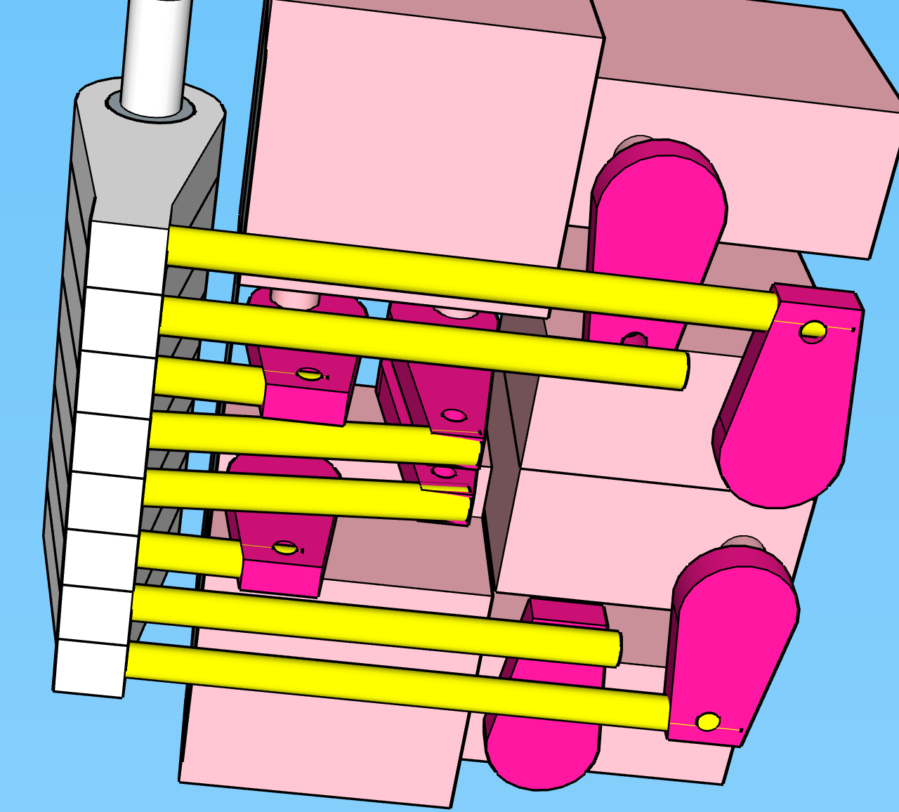
I came up with an idea for a layout where the geometry is such that I’m moving the lever up and down, and had some motors facing upwards and others down. That buys me 17mm of width. Enough for 8 of these:
https://www.amazon.com/gp/product/B07HJYXB4S/ref=ewc_pr_img_2

Two up-down racks would give me 34mm, enough for a larger motor, and perhaps with different geometry I could make both racks respond similarly. Still sketchuping on that one… I’ll post something when I get it figured out.

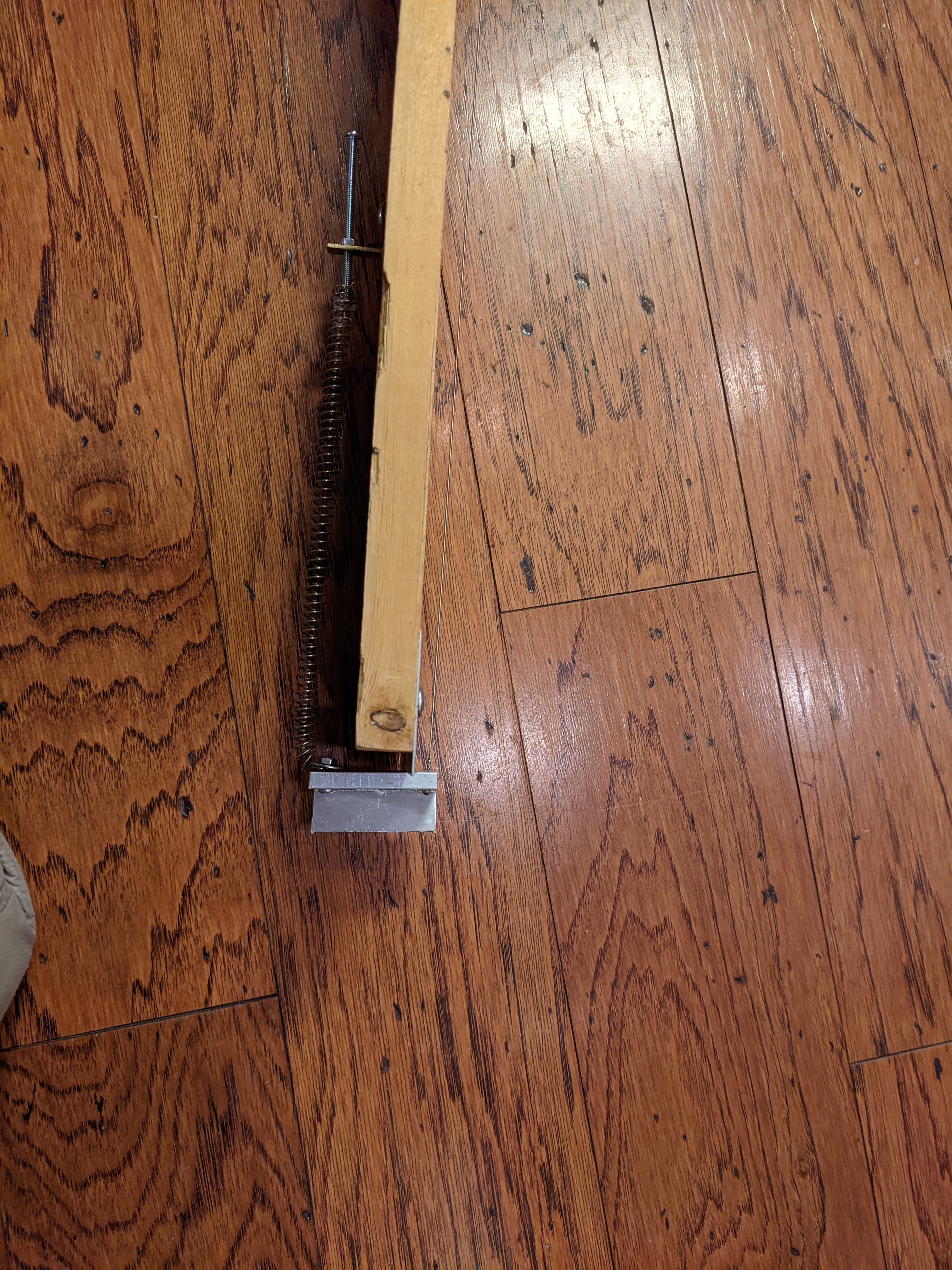
It’s a good point about the cables. Plus they would be very short cables. I’m still worried about stretch or play giving unpredictable results. You wouldn’t want to use them for both pushing and pulling would you? So you wouldn’t want to counter-balance your string TOO accurately. I will say that folks on the steel forum have suggested this is not a real concern, as springs respond differently than strings. So maybe just pulling, with some resistance coming from the lever, is best in that situation. And they will be under far less tension than the ones on the Multi-kord. So yeah, I’ll think on that.

The bridge on many pedal steels consists of a series of changer fingers, one for each string, which have a semi-circular top that the string goes over. As the angle of the changer finger changes, it pulls on the string, changing pitch. But for using a steel bar, it’s crucial that the strings be precisely the same height. That’s why the top is circular about the fulcrum of the motion, so as the pitch changes, the height of the string is unchanged. Hope that’s clear.

In my case, I will probably use a roller bridge I already have, and attach the string to the changer fingers behind it, so that the changer mechanism is not part of the vibrating portion of the string. That will decrease the amount of acoustic motor noise…

1 Like

I admit to not having watched the video, being more of the written word kind of guy (can you tell? :smiley:) but my assumption here has been that your balancing spring can be tuned with a spring to reduce the load on the stepper. To avoid skipped steps you’ll still need to handle acceleration, even with the load balanced. This requires motion planning. Do you know about motion planning for stepper motors? When they talk about a fixed pause between halves of the cycle, that sounds like they aren’t using microstepping and aren’t considering acceleration.

This link explains that difference.

A stepper motor gives lets you control how many steps to take, and reduces or eliminates the need for position feedback. You often still want a “homing” operation where you can sense when the mechanism reaches a limit, but after that as long as you keep power flowing to the motor to hold it in its currently-desired position and it correctly takes every position you command, you don’t need to measure position.

That’s not really how it works. Modern stepper controllers subdivide the steps and give very smooth control through the steps, and can even adjust current many times per step to provide smooth motion. You would want to use these. The Trinamic controllers work this way, and they are what you would want to use for this.

A DC motor controller needs continuous position information, and whenever the mechanism senses that the position is wrong, it drives the motor toward the desired position. Corresponding to the motion planning for the stepper motor, the DC motor controller will have to implement a PID controller algorithm.

Here’s a video on PID controller theory that makes it intuitive based on seeing the impact on physical motion.

A DC motor will have much more torque for its physical size, basically because magnetic fields have inertia and a DC motor doesn’t have to change the magnetic fields as fast as a stepper. Also the DC motor has fewer poles than a stepper.

If you have a dead stepper, disassembling it will be educational! :smiling_face:

Good find on the taps, I was searching for t5 instead of tr5, oops!

The thicker the nut, the more bearing surface and the more friction. So it’s a balance.

You would want an undersized drill bit and a 7mm reamer, in a drill press or mill. You can’t really freehand drill with a reamer. Then you use an arbor press to insert them. Alternatively, yeah you can use a 7mm drill and just use some loctite and make sure the loctite doesn’t get into the bearing! I’ve done that (successfully!)

I assumed that the axle would be supported at every finger; 3mm would be fine with less than 8mm unsupported, but certainly not across the whole thing. But yes there are many many more bearing sizes, and you can choose what fits axle and finger.

A standard M4 is 0.7mm pitch. Other pitches are typically expressed with a qualifier, fine thread M4 is M4x0.5, and there are sometimes other custom pitches.

Usually “lead screw” should mean trapezoidal threadform.

You’ll see TR4.76 listed some places, but that is actually 3/16" ACME lead screw expressed in metric as far as I know.

I see NEMA8 (0.8" / 20mm) steppers with integrated TR4.76 lead screws on aliexpress. For example https://www.aliexpress.com/item/32622031618.html with a POM (delrin) nut.

OK wow I just went down the aliexpress rabbit hole. Here’s a linear actuator including a 10mm stepper and a 2mm lead screw:
https://www.aliexpress.com/item/4001154700714.html

18° per step; it’s a 10 step per rotation motor. I don’t see I can’t tell whether it’s 0.23, 0.25, or 0.5mm lead, and there are no current or torque specifications, but it’s a start.

Here’s one with better specifications and with a hex nut that would be easy to embed in a block. 0.5mm pitch, 25mm travel, 0.5A current, even has torque specified. Don’t worry about 5V — that says you’ll get 0.5A if you apply 5V, but normally you just limit the current and put a higher voltage across; driving it with 24V and 0.5A current limitation would be fine.

https://www.aliexpress.com/item/1005001348928816.html

Same motor specs (I think), 3mm x 1.2mm screw 50mm long, round nut:

https://www.aliexpress.com/item/4000383679456.html

If I were doing this, I would experiment with one of those in the one-string test bed and see whether it would work… If you could stagger the motors you could meet your 8mm pitch requirement, it seems. I’m sure that your balancing spring idea would be key to using such a small actuator! But it might be the key to success here.

Just want to make sure you know that while sketchup is really easy to work with, it’s also modeling surfaces not solids, and therefore is easy to specify parts that are “non-manifold” and can’t turn into models for printing or CNC. Since you’ve done 3D printing you’ve probably run into this already?

Also every conversion I’ve dealt with coming from sketchup has had imprecise measurements and I’ve had to rebuild it in CAD to have precise and correct measurements.

So yes, wire stretches. Heck, when you tighten a bolt, the bolt stretches! But the force on this cable would be much different than a guitar string; the cable is thicker and the force is orders of magnitude lower. You are not going to exceed the elastic limit for the cable, so it won’t stretch meaningfully, I think. And if the cables don’t have much bend, you’ll have very little friction in them.

No, you don’t want to push. Your mental model here is bike brakes not throttle cable. But it takes extremely little return force; I’m surprised how little force every time I play with a return spring. I just replaced a bowden release wire on a piece of furniture and the return spring felt like it was too small to do the job, but no actually it did the job just fine. I wouldn’t worry at all about that. It will be tremendously less force than what the motor would provide. You’ll just tune your balancing spring (you can tension it with a screw, like on a 3D printer extruder) so that you get good return behavior.

these come in various sizes and RPMs:

That’s a nice motor/encoder.
Useful for my “gotta finish that” automated curtain project.
Not much interface data :thinking:

If referencing the link I posted, I grabbed some off ebay and have used them in my project to control them with stepper motor driver signals( Step/Dir ). Code is on github.

oh absolutely, I use fusion 360 once I get serious about a design. Before that I used openscad. But 360 is murder on a laptop because of the limited options for keycommands for navigation, which seems so ridiculous to me. And at this point sketchup is so FAST for me. I did actually make the CAD cutting plans for my keyboard in sketchup and they converted without issue. You have to directionally constrain every possible line, and type in all length values, and if you miss one, you will have lots of corrections to try to find later. This was done before I got a 3d printer:

If you are super careful, it is possible to make real stuff in sketchup, but yeah, its best for experimenting with ideas, mostly. I find if I get into fusion 360 without a really clear plan, I get nowhere.

So thinking through everything you’ve said… I’m not clear why you are leaning towards a stepper rather than a PID motor. It sounds like the motor would have more torque… but harder to wire up and program? I guess the big deal is that it eliminates the whole position sensing issue… which is non-trivial, especially for a test setup.

Those little steppers from Ali are certainly small and cost-effective. I guess I’ll spring for one and see what they can do. I could fit a 15mm version if I can track one
down that size.

No I do not, sounds like time to read up. Good to know there’s a better way to do it.

Yep, same here.

If I thought you didn’t understand the mechanism, I’d recommend watching about 10 seconds at the 4:30 mark. No need to wade through all 5 minutes in any case.

So, if I get one of these steppers, and hook it up to my changer finger… do you have a link for an instructable on wiring it up and programming it, that might be a good starting point? I know how to program an arduino, and I have wires, breadboards, pots, connectors, ribbon cables and resistors handy. Beyond that, I will be, er, stepping into the unknown…

Thanks as always!!
-e

Here’s a 15mm motor… don’t know if this is any better. Just assuming a larger motor is more powerful? It’s cheaper, not that it matters at this price point:

I like the mounting bracket.

1 Like

Bingo. Servo motors with encoders generally cost more, so I was looking for ways that could possibly make sense with a stepper for cost management.

There are two kinds of documentation on using steppers with arduino: Those that show you how to directly control full steps with an H-bridge, and those that use a stepper driver. You are looking for two things, I think:

  • Using a stepper driver
  • More specifically, using a serial interface (instead of STEP/DIR/EN) controls for a Trinamic stepper driver.

Here’s one of a great many resources.

I would use a 3.3V 32-bit card instead of a 5V 8-bit card to control it. It opens up so many options, and they are cheap these days, even in the midst of chip shortages. For example, the Teensy boards go up to 600MHz and are simply not expensive. Here’s a library that works on arduino on Teensy and ESP32, though for this purpose I would probably go with the Teensy.

Absent clearer specs, current and lead together should give you at least some sense of power. They are unlikely to be horribly different in efficiency I think.

Well, I’m comfortable with the teensies, so that’s good news… I’ll put in an order for a couple more. And thanks for the link. Got lots of reading to do now!

2 Likes

Well, when I talked about cost effective, I’m not thinking retail margins. Reading your explanation of stepper motors above, I see:

Using this feedback, the motor can be controlled more smoothly (and typically much more precisely) than a simple stepper motor. Servo motors are much more sophisticated in design than stepper motors and tend to be more expensive, which is why steppers are often used instead.

I want to keep costs down to some degree, but I certainly don’t need a 3-5 dollar solution… if servo technology is better, I feel like I should be looking in that direction, even if it’s a steeper learning curve and more expensive. I mean–how much more expensive are we talking? One thing that would be expensive is putting a lot of time and energy into a second-rate solution to the problem… of course, a large part of that learning will be applicable to the next-gen solution, so maybe no big deal, and start cheap.

Searching, searching…

These are cheap:
https://www.aliexpress.com/item/1005002591809404.html

Do have to figure out the lead screw…

Yeah, when I was thinking about expensive, I was thinking more about things like https://odriverobotics.com/ because I was also thinking of things with pre-packaged servo controllers. Also my interests in servos has been machine control where I’d be replacing NEMA17 or NEMA23 steppers typically. And those packages have come down to the $50-$100 each range in the past few years. But @dougl’s post about controlling cheap servo motors that he linked to above demonstrates how to control h-bridge chips from an arduino, if you have enough channels, with the kind of motor you found! L298N breakout boards with heat sinks are a few dollars each.

Another benefit of servo over stepper is that the servo won’t consume as much power. Classically, steppers have always consumed the same amount of power regardless of whether they are moving. The trinamic drivers allow you to reduce current when they aren’t moving for applications where backdriving forces are minimal, but they still need meaningful current to avoid losing steps, and that current turns into heat. I’d guess orders of magnitude less current to hold for servos than even trinamic-controlled steppers.

A quadrature encoder on a motor doesn’t give you absolute position feedback, so you would still need a homing sensor; for example, a microswitch at one end of travel for each finger, and when you powered up the PSG it would have to sense the home position for each string before being able to count revolutions to keep aligned. Driving a lead screw to limit backdriving, you might be able to get away with “trapezoidal” motion planning instead of a full PID controller, I don’t know. The “trapezoidal” motion planning solution is basically the “P” in PID with a maximum value. There’s probably enough friction in the system to avoid the need for at least the D term, maybe even the I term. That’s gut feeling not science.

Okay, latest re-think.

Looking for servo motors, I kept running into the 180 or 270 degree servos used for RC cars, and there are a ton of them, and they have a lot of torque, up to 50 kg, looks like. (how is this measured? I do not know!) Shouldn’t need near that, but I can get a few samples and see what is needed. It’s what the guy in the first imgur link used for his telecaster mod… My concern was always their bulk. But I decided to address the bulk issue, and it’s not that bad. It looks like I can actually fit them in the space I need:

Not sure if I should use Rods or cable for the pulls. Have to look into what kinds of hardware are available, and what the tolerances are, as I won’t want too much play in the mechanism:

I can’t make all the pulls perfectly right-angle, but I can come quite close:

This is all sketchup, so of course very approximate, but it does prove the concept can work… thoughts?

Are these real servos, not steppers? Will the positioning be precise enough?

The middle two pulls will have the least torque, as I’ll have to use longer levers. But I could just use a stronger servo for those…

Edit: Looks like really precise servos are expensive:

Not quite prohibitive, though…

1 Like

If someone has actually made that work, that’s cool! My concern was that plucking the strings will change the tension and move the lever and cause the motor to react. If I were trying that, I’d definitely use cables instead of rods.

They are real servos, not steppers. Because they have classically used an internal potentiometer for position command, they wear out by wiper wear over time. Basically, you command the position by feeding it a voltage. It turns until the voltage at the potentiometer wiper is equal to the command voltage; it uses the difference between the two voltages as feedback. The change is proportional to how far it is away from the commanded angle (P in PID). Some may have an RC circuit inside as a fixed integrator (I in PID) to reduce “hunting,” I don’t know? Or they might actually use digital logic!

The Dynamixel looks interesting because it says it is programmable with an internal microcontroller! That would be better than the classic inexpensive RC servos. And that could very likely let you avoid reacting to plucking strings by careful parameter tuning.

Note that this kind of servo arrangement will consume power like a stepper, because it is going to have to fight being back-driven all the time; the servos that wouldn’t consume power would be because they are turning a screw. On the other hand, this kind is absolutely positioned, so you wouldn’t have to re-home the fingers every time you turn on power!

Reading here:

Looks like you can get better precision, but you’d still need some external sensing, to control the timing?

Even the expensive robotics servo above has .29 degree precision, which gives about 180 steps of precision over 60 degrees… that’s nowhere near 10 bits.

Well, he was not trying to hold a position in the middle. Forgot about that. Doh! He went endstop to endstop. Not sure how he tuned it though. And nobody has heard from him since he posted 6 it years ago, so it’s hard to ask questions.

I’m realizing these are slow, and probably that’s why they have so much torque… I imagine they all have similar motors inside.

I’m back to thinking about the motors with built-in encoders. Couldn’t find one with a lead screw… wondering how difficult it is to attach a screw… I assume there are adaptors for that sort of thing.

Time to stop Ali diving and mock up this string, so I have a sense of how much power I will need.

Typically you use a lovejoy aka spider aka finger coupling to tolerate imperfect alignment. I assume they are available in very small sizes, but I don’t really know, I haven’t looked.

I definitely don’t know how fast the RC servos are, but if even the most precise aren’t precise enough for you, that puts the nail in this coffin…

If you end up using a stepper, I’d suggest that you consider buying a 3D printer control board with enough channels, rather than building your own hardware. Here’s one with 8 stepper channels: https://www.biqu.equipment/products/bigtreetech-octopus-pro-v1-0-chip-f446 You can get it with 8 TMC2209 stepper drivers for another $20 or so; that seems like a really good deal to me. Looks like the v1.0, v1.1 and pro all share the same firmware, so you can see how Marlin, Klipper, and RepRap are configured for the Octopus and work from there to build custom firmware for it.

I wired up the string tester, but broke my first string. I used the highest string, as suggested by the steel players, but then I found this:

So I can get a particular tension on any string. They are all pretty similar. I think the highest string, being thinnest, is most likely to break. So I’ll be working with a thicker string…

1 Like

Okay, some real-world data, finally. Here’s the test bed:

As my mother used to say, when confronted with something like this: “A thing of beauty is a joy forever!”

Here’s a side view showing the mechanism:

With a 36 gauge string tuned to a low A, there is about 21 lbs of pressure on the bridge. This is near the maximum you would need. It’s pretty well balanced with the spring in the picture. The leverage is about 3:1. Deflection for the desired pitch range is about 1.5 cm, and requires about 3 lbs of pressure. The string returns to center fairly accurately, and it takes more pressure to lower the string than to raise it, 2 lbs vs. 3. My knife edge leaves a bit to be desired, so it’s possible these figures could be lowered a little bit. But it’s a good ballpark.

So now I need to think through the math to figure out how much torque a motor would need to drive a lead screw to move the bridge. With a t5 2 screw with a 1mm thread the mechanical advantage would be… (pi * 5):2, IIRC, or around 8:1…

The encoder motor mentioned previously lists torque figures:
[EDIT: 750 rpm is not in the table, but is available]

If I use the fastest gearing, thats .027 kg.cm. Would it just be 4x the torque at .25 cm from the center of the shaft? If so, that gets us up to about 0.1 kg. If our screw gives us 8:1, then that’s .8 kg, or about 2 lbs. A little shy. But a t5 1 screw or a slower motor gearing could get us there… are those rpm figures at 12v? Can you get more speed with more voltage?

[EDIT: figures are at 6v, and double the speed at 12v!!]

Actually, I think I made my speed calculations based on a 1mm thread, so the slower motor might work just fine with a t5 2 screw, and get us up to about 6 lbs of pressure, which seems like enough margin… I’m not accounting for friction, for example… but these motors are cheap enough I could buy several different gearings. Should buy 2 of each also, in case one is defective…

As far as having to center each time I start up, I don’t think I’d need to. Barring a power outage, the pedals should all be disengaged when power is cut, and the screws will just stay in position until the next power up. You can presume that to be a zero point, and the player will tune the strings based on those positions. Then you can compute the other positions from there, based on the encoder. Seems like it could work. Of course even if it does, it may prove to be less reliable than absolute position sensing, so there might be an upgrade needed eventually.

something like this?

hmmm, that’s as expensive as the motor :wink:

1 Like

Oh, I thought you were going to use a compression spring on the far side of the bridge. But using a longer spring makes a lot of sense for having a similar amount of force through the whole travel!

Yes, all other things being equal, increasing voltage should increase speed.

One more consideration in favor of a stepper motor here…

A stepper motor is a form of brushless motor. Brushless motor voltage ratings are based on current and constant use. You could very likely use 24V to run a stepper motor, but this gear encoder motor is probably brushed, so I wouldn’t go much over the listed 12V. I think that brush wear increases with voltage, but I don’t know if that’s true. With the stepper motor you could probably even go to 28V (the max for the TMC2209) to go even faster. To go over 28V you would have to use TMC5160 which can go all the way to 60V, but is also more expensive. The Octopus Pro can support 60V motor voltage for the TMC5160. I’d definitely try the cheaper TMC2209 first though. (Note that over 50V is considered high voltage, though, so in practice with the TMC5160 I’d stick to a 48V power supply.)

One of the 10mm steppers with integrated shafts I listed above is rated at 6 mN-M at 500PPS at 10 pulses per revolution at 5V, so 50 revolutions per second, and at .5mm lead that’s about 1 inch per second. That’s about .06 kg-cm of torque, which by your calculations definitely isn’t enough. But all other thing being equal, a wider motor has higher torque, and take a look at this 15mm unit, where the force is measured in linear thrust, at 0.5kg:

https://www.aliexpress.com/item/4000834477859.html

That’s 500mA at 9V I think.

We’re getting close to the thrust you need here. Since the current rating is a heat limit and assumes 100% duty, and you aren’t going to be running these constantly, and you can use very low holding current with a modern trinamic stepper controller, it’s not insane to consider running them at substantially more current momentarily. You could very likely safely run 1.5A through them for a few seconds as long as they rest long enough to cool. A 24V system could give you that. With the trinamic drivers, you could ask for 1.5A running current and .1A resting current. It might actually work.

Yeah, or you can have the firmware keep track of the current position for each string in non-volatile storage, and as long as power doesn’t flicker while you are in the middle of a move you are OK.

With the trianamic stepper drivers, they have the ability to sense if they run up against a barrier (by back EMF) and raise a pin to report it. So as long as there is a physical stop fo the fingers at max travel, they could just push the finger until the DIAG signal is raised and use that as an end stop without any switch at all. On 3D printers this is called “sensorless homing” and I have used it on one of the printers I built.

I suppose you could do the same thing with the encoder motors, though! Just drive them until the encoder stops reporting changes for some amount of time, and then you know you’ve hit the end and have homed it; you don’t even need to measure EMF! Sorry I didn’t think of this before…

That’s just a straight hard coupling. And while that seems expensive for a hard coupling, it costs about what I’d expect for a lovejoy / finger / jaw / spider copuling. Wikipedia has a picture at Jaw coupling - Wikipedia

One more reason to consider the steppers that have the integral shaft! :smiling_face:

When the motor shaft is sufficiently smaller than the screw minor diameter, it’s possible to mate them by drilling a matching hole in the end of the screw using a lathe, and then using permanent thread locker like loctite 271 to fix the motor shaft in the hole. But I don’t think that’s the case here? And a metal lathe is more expensive than the motor for sure. :rofl: Similarly, it would be possible to make a small permanent coupling with a lathe and some aluminum stock, and fix it with loctite 271 instead of screws. Do you by any chance have a friend with a lathe? This is a really easy project! Bore a piece to minor diameter long enough for all the parts, then alternate drilling a few mm at wider diameter and parting off through all the pieces you need.