BigMoe I hope no one get afended  when I post here since this is

BigMoe

I hope no one get afended when I post here since this is the closest I get to a group that post builds that can in a way reflect what I’m trying to build, and I’ve been following the group for a while and getting ides, latest Hon Po’s build with spectra-line.

So I have been drawing and trying to figure out this concept for a while now, but got to ask if there are someone with a bit of experience with spectra-line drive for Z-axis who care to comment on my build to see if it’s doable or not?

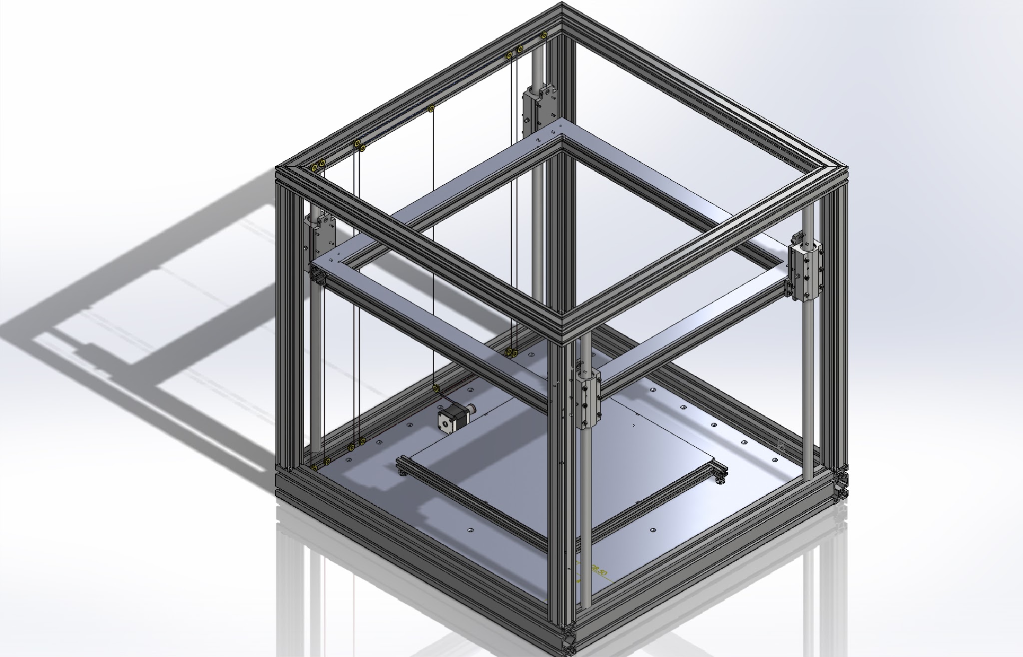
The cube is 800x800x800 mm with printable area like 400x400x400 mm. What I want to try is to let the printed object stay put and lift the gantry with spectra-line to get rid of all the Z-artifacts. I also want to drive the X and Y-axis on the gantry with spectra-line/belt, and if possible use a dual Bowden extruder.

First of all I see it might be a problem with firmware for the combo of spectra-line Z-drive and h-bot or core xy-drive, so I might have to do separate spectra-line drives for all axis, that should work as a regular cartesian setup with belts, I think?

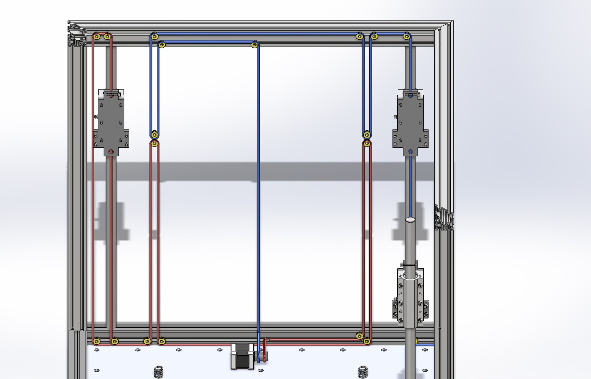
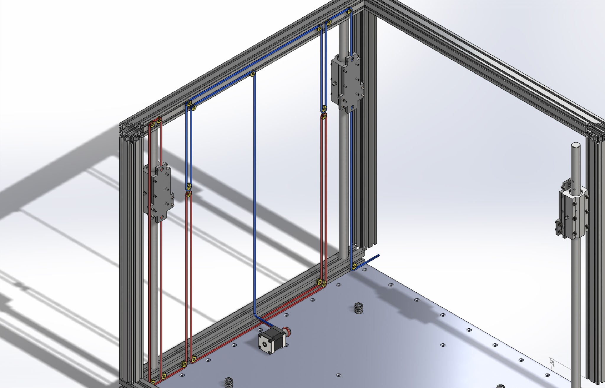
Secondly, I’m not sure I’ve had my head strait on when I tried to alter Nickolas Seward’s concept of a Z-driven axis. What I’ve been trying to do is make a pulley arrangement to help reduce the pulling force needed and even out the pulling over the with of the printer with four attachment points for lifting and lowering. Two directly on the linear bearing house, and two one the gantry.

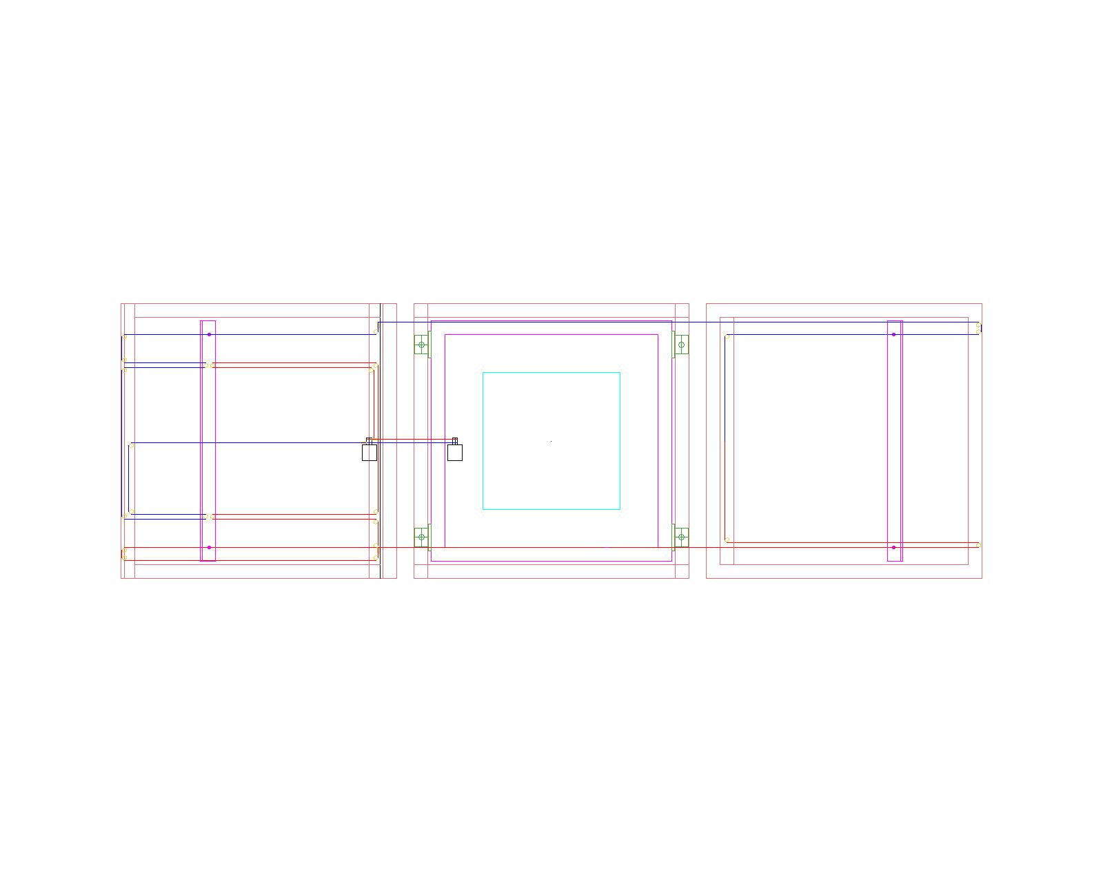
So if you look on the attached drawings I’ve dived the up and down motion in red and blue spectra-lines(beefed up to Ø 5mm just for the showing), and all the idlers in yellow. The four middle one attach to the gantry. It’s not showing yet, but both the outer lines go over to the right side, down under/ to the side of the print-bed. The last picture show the spectra-line layout, from left to bottom to the right side, the pink lines are the gantry I want to lift.

Regarding a dual Bowden setup, I’m a bit afraid the tubes might be a bit long and the pressure to high, approx +1 meter I would think.

All the extrusions are Misumi 40 x 40 mm, on the gantry with milled faces.

Terje

You might want to check out @Shauki’s Quadrap design:
https://plus.google.com/communities/103539262895202172380

Or @Richard_Horne 's Slid3r:

Both make use of string driven z-axis.

This design ads a lot of unnecessary complications. You will need to carry the entire xyz gantry. This will take any and all tolerances and shake them. There will be levels of slop that will imo cause a lot of artifacts at any high acceleration/jerk settings. The UL-T-Slot mk1 used worm gear driven spectra z. Moving up and down for z reduces artifacts as the bed will not shift in x or y planes. And x and y are isolated from excess slop in the z plane. Not to mention that the motors for x and y will need to be carried adding unnecessary mass to an already high mass platform. More Mass means more jerking when reversing directions. There in llies the problems i see at a glance.

I second @D_Rob , can’t see the benefit of driving the gantry instead of the bed. The Z-artifacts caused by unwanted XY movement while driving Z, is already minimized by belt/spectra driven bed already.

By changing from belt drive Z to belt driven gantry, what imperfection that still caused unwanted bed (XY) movement will now caused gantry (XY) movement instead. The same Z artifact would still appears.

Haven’t build anything yet. I was questioning the non integer Z steps may cause artifact when printing metric layer height. I think with big enough Z step value, the Z resolution is good enough that any round off error will not cause problem.

My 2c…

4040 is huge, and expensive, and unnecessary. 2020 is remarkably strong - more than strong enough for such a machine, given suitable bracing - but you have no bracing. You have all your ‘square’ components made from 45deg angled cuts. Where is the strength in those joins coming from? How are you joining the uprights when the obvious place to screw them together is in the middle of a 45 degree jon? Drilled, screwed butt joints are far superior in working with aluminium extrusion - as long as your cuts are dead on 90deg. (as an example, a large rectangle I just cut with my indexed drop saw, when just butt-bolted together delivered angles measured at 90.01 and 89.99, respectively with a digital angle gauge. Nothing special done - just cut and drilled the ends and used self-tapping bolts. Pulled together on a large table using nothing more than the torque-limiting ability of my battery drill. I was pleasantly surprised - but then I did spend half an hour indexing my drop saw, so it was vindication of the effort.) It seems you are over-complicating the construction of a box.

I have also got a moveable z-axis using spectra - essentially Rich’s Sli3Der, but made from MDF. I have made some efforts to reduce the likelihood of the bed being out of true: The gantry is extended below the table for some distance and bearings are at the extents (150mm between them), giving a longer bearing footprint to resist deflection. The gantry is very solid - made from routed, screwed and glued 18mm and 12mm MDF. It’s still light, in comparison to a metal gantry, and in the guise of a 3D printer, no less sturdy, but it was machined and built up from solid pieces using a CNC router, which gives it a positional accuracy not available with extrusion and printed parts. I could make the chassis from any sheet-goods - ply, alloy, acrylic, phenolic board, MDF - it doesn’t matter, the relative dimensions will stay fixed due to the rigidity of the materials. With extrusion, there will always be an element of tuning and adjustment. You want to limit those areas where you have to adjust to the bare minimum.

With your design, you have introduced lots, rather than worked to reduce them.

Another 2c: Make 2 squares of 2020 to your 800mm dimensions, butt joint them in sequence (so only 4 screws) and check for square. If your cutting tool was accurate, you will have pretty close to dead on 90 deg corners. Join those two squares with 4 pieces of extrusion joined through the ends by 8 self-tapping hex bolts. Check for square again.

That should result in a really rigid box, to which you can add internal braces and 36 10c corner brackets to firm it up. Assuming your x and y-axes aren’t too heavy, it shouldn’t move when you print.

Overcomplication and overengineering… can be fun, but I’ve never been a fan of reinventing the wheel.

Thank you all for your comments.

It have been one of my main concerns if the moving gantry will introduce artifacts, that’s why I have tried to get the gantry as rigid as possible, with a solid aluminium plate cut out on top to make it absolutely square and as torsionally rigid as possible. My smooth rod are Ø 20 mm and my linear bearing houses are 120 mm long, I’m hoping this will add to the rigidity of the machine.

In such a big printer a guess the bed will be has heavy as the gantry, with base for the bed, insulation, heat-spreader, heaters and glass on top, and you will always have the issue with the bed not being aligned(but I guess the gantry can get out of alignment also).

I haven’t really been focusing on the assemble of the frame yet, I just mucked it together to be able to try out the spectra-line setup, and absolutely agree on not using 45 degree cuts. As to the 40 mm size, it’s a bit over-engineered, but as such a big printer I think it will look better with 40x40 mm, then with 20x20 mm.

Has anyone tried or know of anyone who has tried to build one with moving gantry?

For the time being, what I really need help with is the layout of the spectra-line, will it work as laid-out in my schematic? I guess it will be the same layout whether I move the bed or the gantry.

I will see the coming weekend if I can come up with a version with a moving bed, and maybe calculate the weight of the gantry and bed.

@Terje_Moe for a moving gantry see @anon57870006​ and his ringrap

1 Like