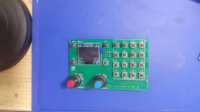
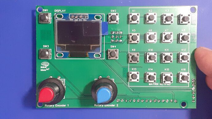
A simple IO Panel ( with keypad, buttons, encoders and a display ) that I made to make life easier during project design and testing

Multi-Purpose IO Card

When we are working on a prototype, we always need access to pushbuttons, encoders and even displays to test our ideas in the real world. This Multi-Purpose IO Card was designed to help me do just that…

What is on the PCB?

This PCB was designed with my particular work style in mind. I use a lot of I2C devices, IO Expanders, Displays and sensors. It would thus make sense to have I2C on the PCB, to control an OLED display, as well as a PCF8574 IO expander, that is used to drive a 4×4 Matrix Keypad. Two Rotary encoders, as well as another 4 standard push buttons completes the PCB…

The features, summarised is as follows:

1x Matrix Keypad (4×4) Controlled via an PCF8574 IO expander with selectable addressing.
1x SSD1306 OLED I2C Display
4x Momentary pushbuttons, configured to be used with internal pullups – i.e pushing the button pulls the GPIO LOW
2x Rotary Encoders, with integrated Pushbutton, also configured as Active LOW

The board has all of the connectors and jumpers on the back, making it possible to mount it to an enclosure as a control panel.

I have also provided an additional I2C header to make it possible to add additional devices to the I2C bus easily

The PCB in Detail

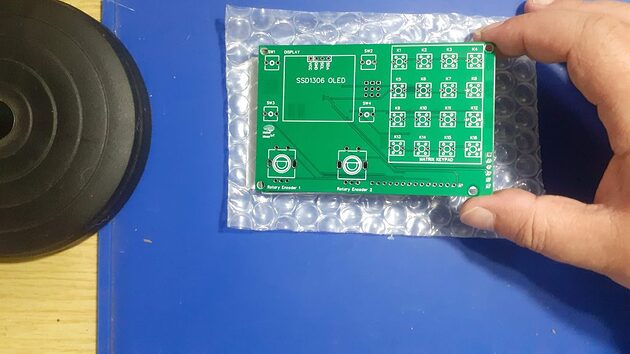
PCB Top

Starting from left to right, we have two push-buttons, an OLED display, with two rotary encoders below the display, and another two momentary push buttons. On the Right, we have a 4×4 matrix keypad, and various pin headers for connection to a microcontroller of your choice.

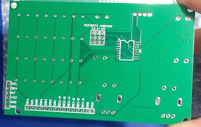
On the back, we have the PCF8574 IO expander for the Matric keypad, addressing Jumpers for the IO expander, as well as the two pin headers for connections to and from a microcontroller…

The Pinouts of these are as follows:
Horizontal 15 pin 2.54mm connector
SDA I2C Data
SCA I2C Clock

GND

SW4 Momentary Push Button 4
SW3 Momentary Push Button 3
SW2 Momentary Push Button 2
SW1 Momentary Push Button 1

RE2-D Rotary Encoder 2 Push Button
RE2-B Rotary Encoder 2 Pin B
RE2-A Rotary Encoder 2 Pin A

RE1-D Rotary Encoder 1 Push Button
RE1-B Rotary Encoder 1 Pin B
RE1-A Rotary Encoder 1 Pin A

GND
VCC 3.3v to 5v DC

The Expansion header extends the I2C Bus, as well as proved access to the interrupt pin on the PCF8574. VCC and GND are also provided.

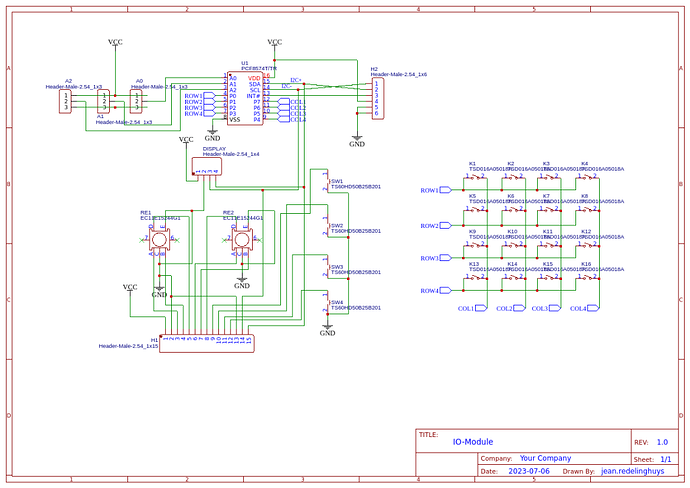
The Schematic

Manufacturing the PCB

The PCB for this project was sponsored by PCBWay .

Disclaimer:
Clicking on the PCBWay link will take you to the PCBWay website. It will enable you to get a $5.00 USD voucher towards your first PCB order. (Only if you sign up for a free account).
I shall also receive a 10% commission AT NO COST to you if, and only if, a paid order is generated from the click on this link.

Assembly and Testing

The assembly of this PCB was relatively easy, as it contains only a single SMD component. I do however have to alert you to a certain caveat…

On the PCB, the I2C OLED display pinout is, from left to right,

VCC GND SDC SDA

I have however come across similar displays that swap the GND and VCC pins… and some that even have SCL and SDA swapped…

It is thus quite important that you check your display BEFORE soldering it to this PCB…

Addressing the PCF8574 is also quite easy, with the jumper towards the top is a high, and towards the bottom is a low… They are marked A2 A1 A0 and thus, counting in binary, all low will be 0x20h and all high will be ox27h

Also, note that there are NO I2C Pullup resistors on the board. My microcontroller PCB’s usually have these already, and most I2C Sensors, including the OLED Display that we use, already include as well…
You should thus check what you have on your own hardware, as it is quite impossible to cater for every situation… In a future version, I may add selectable pullup resistors onto this board as well…

Coding and Firmware

The possible uses of this board is quite broad, and the code possibilities are thus also quite extensive. Since I mainly use ESPHome or the Arduino IDE with most of my projects, I wont be including any specialised code here. I think it is enough to say that almost all of the available PCF8574 Matrix Keypad libraries available for the Arduino IDE will fork with this board…

The pinouts are important, and thus :

Row 0 – P0
Row 1 – P1
Row 2 – P2
Row 4 – P3

Col 0 – P7
Col 1 – P6
Col 2 – P5
Col 3 – P4

As far as ESPHome goes, you will need to

  1. Add an I2c bus for your device
    2)Add a PCF8574 component
    3)Add a Matrix Keypad component, and refer the rows and columns to the pins on the PCF8574 – See below for an example of how I have done that in a previous project.
#I2C bus

i2c:

sda: 4

scl: 5

scan: true

id: I2C_Bus

#
# In my case, SDA is on GPIO4 and SCL is on GPIO5
# This is similar to the standard configuration on a NodeMCU v2 Dev board
#

#
# The next step is to configure the actual IO Expander, which in my case is located 
# at address 0x27
#

#PCF8574

pcf8574:

- id: 'pcf8574_hub'

address: 0x27

pcf8575: false


#
# Now we can add the actual keypad interface to the YAML file
# Take note of the difference from the ESP32 file above.
#
#

#KEYPAD

matrix_keypad:

id: mykeypad

rows:

- pin:

pcf8574: pcf8574_hub

# Use pin number 0

number: 0

# In the ESP32 file, we wHereould specify a pin directly like:
#
# -pin: 17
#
# That approach will not work for us.
# The reason for that is that we have to redirect the GPIO to a 
# physical pin on the PCF8574 IO expander.
#
# That is done with the following syntax
#
# - pin:
#pcf8574: pcf8574_hub -- This is the ID of the PCF8574 device -
#number: 0 -- The actual pin number

- pin:

pcf8574: pcf8574_hub

# Use pin number 0

number: 1

- pin:

pcf8574: pcf8574_hub

# Use pin number 0

number: 2

- pin:

pcf8574: pcf8574_hub

# Use pin number 0

number: 3

columns:

- pin:

pcf8574: pcf8574_hub

# Use pin number 0

number: 7

- pin:

pcf8574: pcf8574_hub

# Use pin number 0

number: 6

- pin:

pcf8574: pcf8574_hub

# Use pin number 0

number: 5

- pin:

pcf8574: pcf8574_hub

# Use pin number 0

number: 4

keys: "123A456B789C*0#D"

has_diodes: false

The Rotary encoders and momentary push-buttons can be handled in the same manner, using standard libraries in the Arduino IDE, or a rotary encoder component in ESPHome…

The OLED display would also be handled as above, with a DISPLAY component in ESPHome…

Summary and next steps

The next steps, for me at least, would be to design and CNC cut a suitable enclosure for the IO panel/Control panel in order to make it easier to use…

The panel was designed to be a tool to aid me while designing, and part of my never-ending battle getting rid of breadboards.

It does its job well, at least so far, and works as I have intended it to.
3 Likes

Thanks for sharing, interesting. I had a similar aha!

I hate the time it takes to breadboard an embedded controller project. This is especially true of through-hole designs where soldering and wiring the core elements into some kind of matrix board is a pain as is the external cabling. To make matters worse the board layout ends up poorly documented and the form factor followed whatever perf board I have laying around. Then when I am done with the testing I would still have to go design a PCB. The finished proto was much larger than it needed to be because I was still working with through-hole components. Proto-boarding SMT is challenging.

In the process of moving to SMT and getting to a free PCB design tool chain, it dawned on me that I should go directly to an SMT proto. Even if I had to buy 5 boards and throw 4 away the resulting cost/time/size/reliability benefit would be worth it.
I landed on EasyEDA for the toolchain as they provided the capture and PCB design tools and made it really easy to order boards at a reasonable price.

On my way up the SMT learning curve (still climbing), I realized that these controller projects always included one or more of these off-the-shelf modules:

  • An Arduino module (most of the time a Nano, Wemos, NodeMcu)
  • One or more sensor modules; current, hall, switch, accelerometer, A/D, various radio
  • Local display: 64 & 32 char
  • Switches, buttons, LED’s
  • Misc: resistors, caps, inductors
  • Multiple sizes of .1 pitch connectors
  • Power: 12V, 5V, 3.3V regulators

I also realized that most of the time the interfaces were:

  • Direct I/O to the processor
  • I2C
  • Wifi
  • Radio i.e. 433mhz

So I set out to design a universal [usually there is no such thing] PCB platform that I could build most any project on by socketing and soldering modules and components. I would somewhat standardize on components and modules but still be able to hack unexpected modules into compatible sockets. I expected this board would be larger than a custom design could be. If I wanted to go to a production size and configuration it would be a simple matter of returning to the PCB platform, making a copy, deleting parts, and ordering the new form factor.

Common busses are routed on the PCB and can be cut loose or rewired as needed. Parallel pads/holes exist to facilitate making the connections between parts and I/o connections with discrete wires. I like to use wire-wrap wire. Power buses are configurable with jumpers.
In the event that a new module, that has a different pinout, is needed, you can plug it into one of the header rows and wire it up.

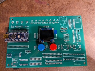
Here is what I came up with:
This is a photo of the first version. I have not ordered or tested the newest version.
I found out that every time I use the platform I want more stuff added.

The newest version supports:

  • Multiple-size processor modules (nano, Wemos, NodeMcu)
  • Multiple power supply configurations
  • Prewired: SDA, SDL buss
  • Sensors: 5, 6, 8,10 pin modules
  • Display; 16/32
  • 4 buttons/ switches
  • 8 random resistors
  • 4 random LED’s
  • 2 pots
  • 12/5/3.3 V power regulators
  • Jumper header for configuring parts
  • 6,8,12,16 pin headers, for I/O or other hacks of sensor modules
  • Int/ext Power fuse
  • 12VDC power jack
  • Ext 12VDC power out
  • Just realized I should add some cap pads

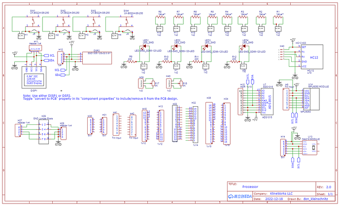
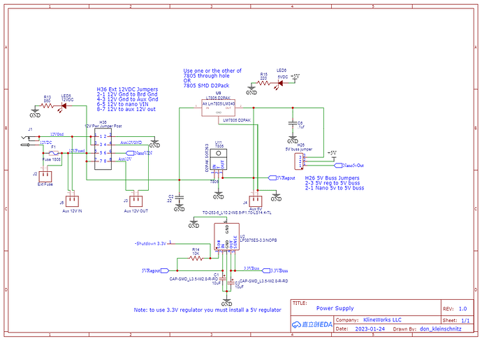
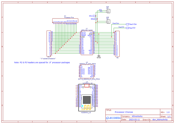
This is a current schematic which is a WIP & untested

3 Likes

This is very impressive…

I have the exact same problem. I started with TH components all those years ago, and only in the past 5 years really got into SMT stuff,

More these days since I invested in buying all the equipment I need to properly assemble them. Hot air is not always a solution, and hand soldering anything smaller than 0805 just looks so messy!

I made a similar board, actually a solderable breadboard, with a lot of SMD pads on there. It is cheap enough to use once and chuck it when I am done.

Easy EDA is also my goto PCB design suite. I am too lazy to import all the libraries into KiCad everytime I want to do something,

The integrated LCSC database inside EasyEDA really speeds up my design cycle, as I can choose a component in realtime, get stock levels, check datasheets and get the footprint at the same time.

This latest IO board is just another one of my toolset that I have built for my own use over a long time… I also really hate the mess that comes with breadboarding, to the extent that I will sometimes choose to have loose PCB modules connected with wires rather than touch the breadboard…

With analog circuits in particular, the added stray capacitance and interference those things add is just unbelievable…

SMT is challenging, especially the QFN and smaller packages… Stencils cost money, and are generally used once… BUT they make assembly just so much easier, and the end result so much more beautiful :slight_smile:

Stay with it, SMT gets easier ( if only my eyes would agree with me there - as it is I need a microscope for most of the jobs these days :slight_smile: )

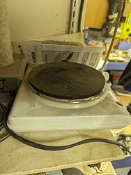
I bought this to do some desoldering but it actually works well soldering with SMD parts.

https://www.amazon.com/gp/aw/d/B08R8XZDMV

Exactly how are you using this for PCB?

You lay your PC board on this with solder paste and it melts the solder paste. You can also use it to desolder SMD parts.

There are a lot of YouTube videos showing how to use them.

I heats the entire board?

Yes. It is a flat plate with a heater.

Then would a hot plate work?

BTW thanks, it’s been a while since you coerced me into buying a tool. Lol

1 Like

This is probably one of the cheapest tools I’ve recommended!

interesting…

I bough a Chinese hotplate, that they use for mobile phone motherboard repairs… was quite expensive at about 200USD but rock solid. goes up to 480 degrees C, so also ok for that pesky lead-free solder. Been happy with this one. much more even heating than the hot air, and it has a big 20x20cm bed…

only drawback so far, is that it take quite a long time to cool down, so I have to either do a few boards at a time, of wait a few hours between boards ( That is not strictly a thing, But i prefer not to add a cold PCB onto a hot area, as I believe that the heat might cause a bit too much stress…

For desoldering, nothing beats the hot air though, but at the same time, I have my eye on one of those tiny “desoldering hotplates”… but those are still a bit expensive :slight_smile:

3 Likes

@HalfNormal are you running that plate with 110 and does that provide enough heat?

Yes and Yes

1 Like

@HalfNormal,
Do you use a temp controller with the “hot plate” that I bought from above?
This thing hits 330F before I unplugged it.
230-240F should be the reflow range, right?

I also noticed that the screws mounting the feet would hold the board above the surface. Do you remove them or is that a good thing.

Would a standard hot plate work (which has temp control) just as well?

I do not use a temperature control since it works for what I’ve been using it for. As for the screws, again I have not used it for larger PC boards. I thought about countersinking those screws if I do use larger boards. It heats the PC board up and does not damage it as far as I can tell.

I’m sure you could use a hot plate as long as it heats up hot enough to flow the solder you are using and the surface is flat enough for an even heat distribution.

1 Like