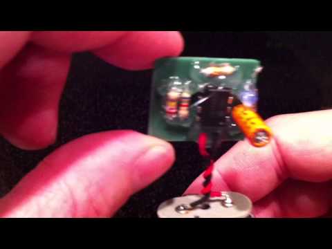
3D printable PCB proof-of-concept! #printrbot
Using up some of those ancient spare parts in the garage… I think in the video I misspoke and said “completely 3D printed” but I meant “completely 3D printable”. The traces were filled by hand in this case, but there is no reason the filling can’t be automated using a second “extruder”.
hadn’t seen this one 
Wow.
hell yes!!!
You could simply fill the whole back side of the board then sand it down
@Camerin_hahn I’ll add that to the list of things to try. I’m not sure how “sandable” the paint is though. It’s pretty soft. But just squeegeeing the conductive paint onto the board would be fantastic if it works! Definitely worth a try! Thanks!
The squeegee would be better, then sanding the substraight remove unintentional shorts, I have seen some sensors made conductive filament (cap touch). I have played with some alternative materials for making circuits (thread copper fabric, copper tapes, conductive inks conductive epoxies) There is many issues with using all of these thing you the best of luck. Some challenges that you will face include resistance, voltage drop, expense and stabilities. but my guess is you are tinkering, like I have been.
Any ideas how to convert a fritzing diagram to openSCad or STL?
@Dru_Jensen I’m not familiar with Fritzing. Does it export gerbers and drill files? All EDA software should export those formats. Those would be the formats to convert to OpenSCAD or STL. I haven’t seen that conversion software anywhere personally but plan on looking. If I can’t find a toolchain then I may try to write a tool.
@Jerrill_Johnson Yes. http://fritzing.org/ Its an open source tool to easily create PCB’s.
How did you design the board? In OpenSCAD?
I used FreeCAD to generate the printable STL. I usually use gEDA to do schematic and PCB design normally, but the circuit was simple enough that I could just draw it and be confident about not screwing something up. I’ll have to check Fritzing out though. It looks like it does support gerber export. Any tool that can take gerbers to OpenSCAD or the like with have the broadest utility I think. There’s still a lot of work to do to determine what the STL generated from the gerber should look like though to make putting one together easy. I wouldn’t call what I did here easy exactly and definitely wouldn’t want to use this process on a larger board. R&D continues…
@Jerrill_Johnson I found this on thingaverse:
Looks like he hasn’t tried it yet. Maybe the combination of your technique with his just might work. This would be way cool!
Very cool
Awesome. Thanks for sharing!
wow tool
Fantastic work!
is there a specific reason for not going the " remove copper from a plated pcb " with a cutting bit or by applying photo resist (ok this one is …yuk acids) , besides the general fad of adding material like reprap/makerbot ? i do find extrusion interesting for working with platics in general , but these projects just limit themselves in availlable material , i’m working on a bootrap and hoping to work with a larger range of material like wood and metal in addition to extruding plastic
