Work in progress: Tuning the MSGEQ7 readings.
First step: Improving the signal quality by adding a 33pF capacitor between the MSGEQ7 output and ground.
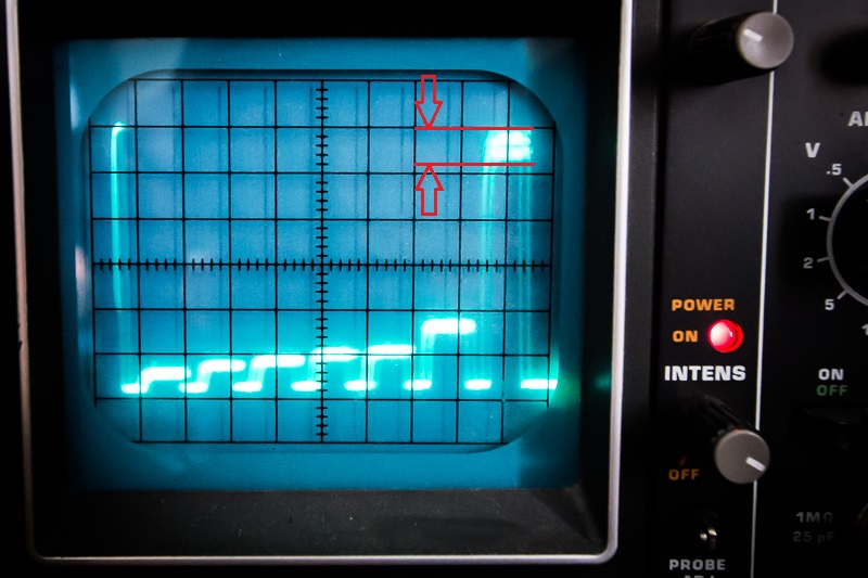
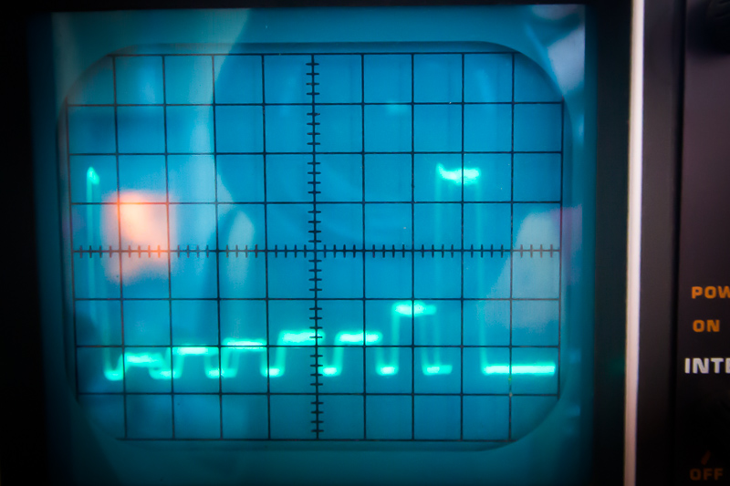
On the pictures the output signal from the analyzer when I feed in a 16 kHz sine wave.
On the left picture the standard output from the spectrum shield. Please note the signal range of the 16 kHz band between the red arrows. Like 0,4 V fluctuation. Not good.
On the right picture the same signal smoothed by the additional capacity. Looks better.
X scale is 20 µS by the way. To become accelerated…
That sure looks like an analog scope. How can you tell the difference between 0.4V of noise/fluctuation, versus 0.4V of actual bona-fide variation in the signal each time the scope retraces the display? Does the MSGEQ7 have a stable, unchanging, low-noise test waveform at its input? If you’re testing with music or live audio, wouldn’t variation in the signal levels be the expected result?
Good questions, Paul! I used a signal generator running in the browser (http://onlinetonegenerator.com/) on the PC and had an external Audio DAC feeding the MSGEQ7. After your question I scoped this audio signal and found that is it not as clean as I assumed. Thanks for the hint!
If you have a Teensy 3.1 or 3.2, I’d be curious to hear how this compares to using the audio library ADC input and FFT analysis object?
MSGEQ7 is definitely noisy. I’ve also had good results putting a 22pF capacitor between the MSGEQ7 input and it’s virtual ground (the rail split GND pin next to the input).
Is it possible to use the Teensy 3.1 ADC without the Audio Adaptor Board, @PaulStoffregen ?
Yes, you can use the on-chip ADC instead. Or you can use it together too, for 3 channels input. But the ADC quality isn’t as good as the shield, only about 12-13 bits performance.
There are people out there that use 100 nF capacitors on analog input instead of the (regarding the spec) required 10 nF. Do you mind checking that?
My MSGEQ7 arrived yesterday, I hope to find some time for assembly and tests this weekend…
Interim findings: With my setup 27 µS settling time for the MSGEQ7 output is the absolute limit when expecting precise results. That means with classical Arduino functions I get a comple stereo 2x7 band measurement in 338 µS. If I don’t reset the MSGEQ7 every time (why should I?) and use FastLEDs FastPin function instead of digitalWrite I get data within 331 µS. If I set the ADC resolution down to 8 bit I get the results within 260 µS. I think something between 195-200 µS is achievable by completely recofigurating the ADC. But the bottleneck is the time the output needs to become stable - 189 µS just for waiting.
I’m really curious if software FFT will outperform this.
Most probably not on AVR. A Teensy could do…
(Unfortunately, I couldn’t find some time this weekend. The concept “family” takes a lot of resources…)
Yes, talking about a Teensy 3.1 programmed with the Arduino IDE.