What settings do you use to get decent grayscale representation with a K40 and smoothieboard (Cohesion ReMix)?
I will say that the first bottom to top from the right is very good, darker is not seen but surely is deep. That changes with the material
I tend to run @300mm/s 200usec pulse duration and vary from 0-50%, 0-75%, and 0-100% depending on substrate and desired depth. Pot set at 10-12ma. 200 usec seems to have a more even gradient than 20 and 400 didn’t change much.
Following 
Are the patterns in the pict above all run at different times and settings? Do you have a pot installed?
Because I was not able to set the current lower than about 3-4mA with the pot, I had to generate the gcode with only 0-10% power at 100mm/s. With that same gcode i have run the job several times with different PWM periods between 20 and 300us. Shorter periods get deeper burns, but not darker. The right column was with 200us. Then I played with the feed. But I am not satisfied yet.
It looks like I have too much power, but if I go faster, it gets deeper, but not as dark.
+Peter van der Walt I did also test with LW3 and different feeds for black and white, but the difference was not much.
A am not satisfied yet, because it looks like I got better grayscale with the moshi board. Will test furter…
@cprezzi what speeds are you getting?
currently doing similar tests with the fabkit, but the max speed before jitter is really unreliable so while we manage to get an okay gradient like you are testing now the second we do a complex grey scale the speed is out the window and every thing burns :S
I find that 185-200us is the sweet spot for pwm period. Also I typically run with a bit of “tickle power” meaning I increase the minimum power in the firmware between .03 and .05 (3-5%) I hope you have the potentiometer still connected as I set my ceiling power on it for engraving at no more than 10ma 7-9 ma usually gets me what I need. I also found that focus of the laser can contribute to the darken of an engrave around 1-2 mm usually works best for me
Doesn’t the moshi board dither not greyscale?
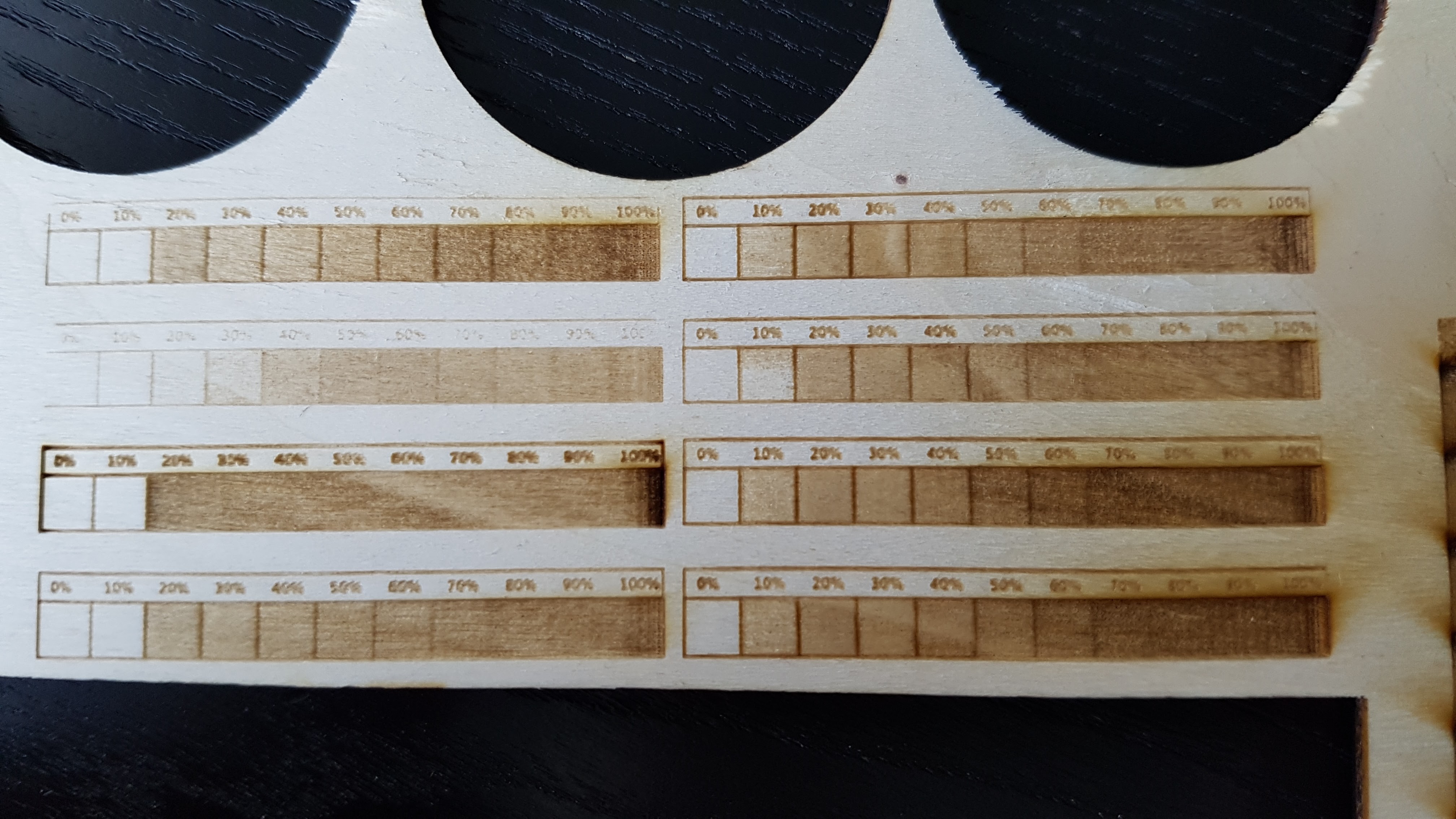
I have not done a good job explaining this theory nor had the time to create a proof of principle that converts it to practice but this is what I believe is the characteristics of the power K40 control system configured like we have it:
- The gray scale granularity is controlled by the Gcode values. Therefore the GCode should create S values to get the full scale grey-toning. Adjusting the max/min S values by Gcode reduces the grey scale range.
- The POT adjusts the overall intensity. If the pots setting is high it overloads the S values and essentially reduces their effect and in turn the grey scale granularity. You want the pot to be set at the minimal value to get good black at the top of the grey scale range for the material and speed. You need the pot to be able to control contrast based on materials and laser degredation.
- When both are adjusted at the same time the results can be hard to rationalize because: Actualpower = S value_df * Pot_df
I expect that the best results would be leaving the S range at its highest value and then increase and decrease the pot to get the best contrast.
I am also convinced: there is an unsolvable relationship between PWM period and laser tube response, at least that is what the model shows. Increasing PWM period allows better laser response but reduces power control granularity. This is why it gets better up to 200us and then only minor improvements at higher values.
I believe the solution is to control the power of a pixel separately from its on/off state. I am doing some early design/testing work in that direction.
@Alex_Krause all that makes sense (see my post above) with the addition that changing focus (spot size) changes the overlap between scans and therefore the exposure of the marked image.
Its also important to insure the the machine is marking at the correct resolution in X and Y which the actual spot size vs the spot setting used to create scans.
The spot gets larger as the beam is in-out of focus.
@donkjr I think you are absolutelly right with all you write.
I’d like to use the full S-range of 0 to 100% (for best dynamic range), but then I get too much power, and I am already at the minimum setting of the pot. Any lower, and it doesn’t lase at all.
Could it be a problem that I have connected the L pin of the LPS to the heatbed mosfet - pin?
It looks like the mixing of pot voltage and pwm switching is not linear at all.
I will quickly swap the moshi board back and try to measure the LO signal output with my DSO to see what’s different 
@cprezzi ok that is interesting I have not heard or realized that at the lowest Pot power setting the marking power is to high. I need to think about that :).
I have never looked at the LO but since there is no connection to the IN (power control) I assumed that the LO signal simply provided pixel on/off control, not PWM, and raster’s are dithered in the software.
@cprezzi
“It looks like the mixing of pot voltage and pwm switching is not linear at all.”
I have it on my list to look at the internal LPS PWM across the range of LO (PWM) inputs … have to up the priority.
@cprezzi it’s ok if you have the pwm to L, is not interfering the pot, indeed moshi regulation is done with L …
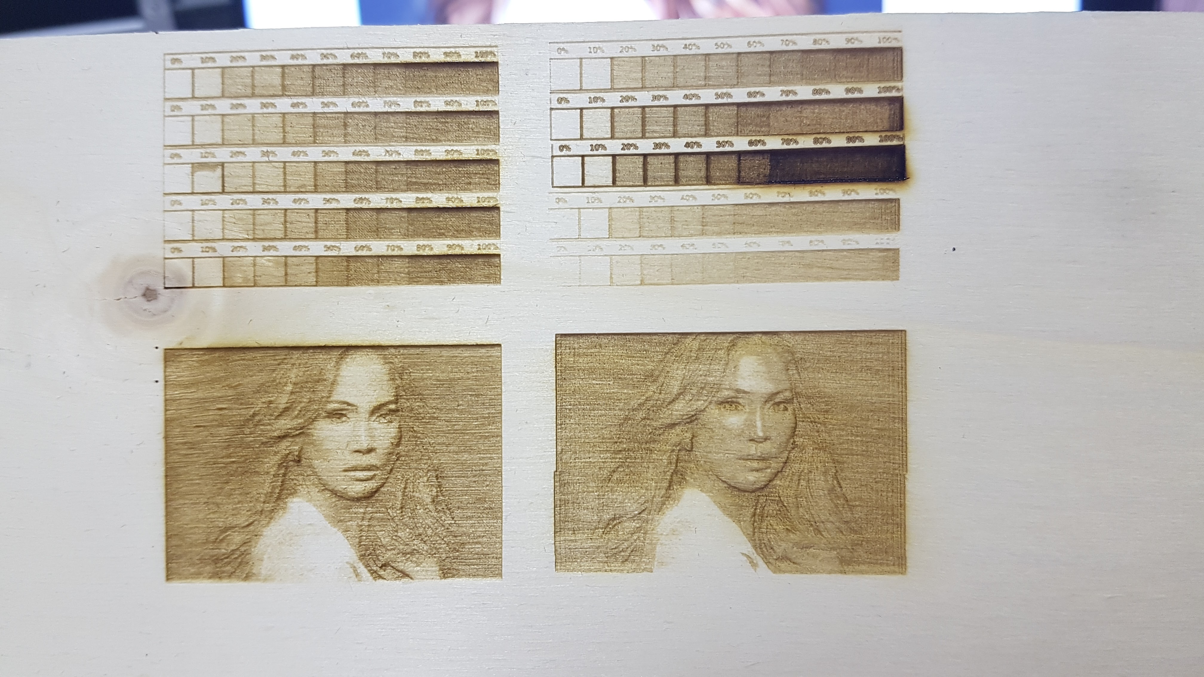
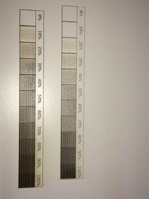
The grayscales on the left (moshi) was all made with the same default settings (1000dpi, 100mm/s, minimal current), on the right I tried to reach the same result with LW4 (same current, 200us PWM period). From bottom to top:
- 100mm/s, 0-100%, 0.2mm laser diameter
- 100mm/s, 0-100%, 0.1mm laser diameter
- 100mm/s, 0-100%, 0.0254mm laser diameter (=1000dpi)
- 100mm/s, 0-100%, 0.05mm laser diameter
- 80mm/s, 0-70%, 0.1mm laser diameter
The left picture was made with 1000dpi, 100mm/s, the right with 80mm/s, 0-70%, 0.1mm laser diameter.
can you post the files/g code so i can compare results? I am not getting anywhere near 80mm/s without jitter with LW4
I wasn’t able to completely capture the moshi LO signal because I only had a tiny DS203 available, but it looks like the moshi board doesn’t use PWM. Instead, it looks like some pulse density modulation with a constant 50% duty cycle, which could be dithering.