I don’t remember seeing this here, but then I didn’t check exhaustively.
Sometimes it can be a little mysterious why the laser isn’t firing when a water flow or interlock switch is misbehaving. Make the actual switches operate a 5V DIP relay with DPDT contacts, one per switch. Wire one of the sections in the relay to echo the original switch contact, the other to run a control panel LED. With this in place you will know at a glance that the interlock or water switch is open so the laser not firing is not mysterious, at least for these conditions.
2 Likes
Good idea…
I solved this problem by adding an LED to the interlock line with a pull-up to 5V.
1 Like
That’s a good idea too. I considered that first, but decided that having an isolated secondary switch that could float around at whatever voltage and current the original switch did and not muck with the original receiver terminals was a good goal. The K40 power supply tolerates this, as you found out, but I was being a bit more conservative.
Since I posted that, I did some looking around in the Mouser Electronics catalog and improved it a bit. Water switches, interlock switches, thermal switches and [whatever] can be replaced by the output side of a MOSFET output SSR. I went with the cheap DPDT DIP relay for isolation’s sake and the need to have an inverting action, turning on the indicator LED when the switch is open. It turns out that you can use the original water (or whatever) switch not float, but have a pullup to +5 and a connection to the SSR’s internal LED through a resistor. So when the switch closes, the SSR is on and the output side of the SSR is on. These things saturate to about half an ohm, so it’s a fair model of a dry switch contact. I added a TO-92 MOSFET like a 2N7000 with its source to ground and its gate to the water switch, and a resistor/LED between +5V and the drain.
When the water switch is on, current flows through the SSR input and output, and the MOSFET gate is shorted to ground, so the indicator LED is off. When the water switch opens, the SSR goes off, and the MOSFET gate is pulled up, no longer shorted by the water switch; so the indicator LED goes on.
I can post a schematic if that would help. The SSR is about US $1.50 at Mouser, a 2N7000 is about $0.20. I started to do a PCB layout for about three of these on a board for ease of integration, but it’s so trivial that I think most readers would just hack one or two on perfboard.
Keep in mind that true safety interlock circuits for these kinds of devices (laser/HV) should not have electronic devices in series with the interlock circuit 
Yep, been there. I’ve been taught at by certified experts in reliability and safety over the years. I’m well aware of the dictum that adding a part adds ways to fail and increases the failure rate.
If you think about it, the logical conclusion of that line of thought on the K40 and interlocks gets rapidly down to the interlock(s) having to interrupt the AC power before the power supply to avoid any reliance on the insides of the power supply. The K40 Laser On switch relies on the inside parts in the power supply to be completely functional to lock the beam out. It’s already impure in that line of reasoning.
We’re not likely to be able to get the uninfomed user to rewire interlocks to interrupt the AC mains, and it might well be a positive danger to the uninformed to tell them to go rewiring their AC, so we’re left considering how much worse or better, and in what way any other additions might be.
Tinkering with the low voltage circuit of the Laser On switch seems to be where most people land. In light of that, a circuit in series with the Laser On switch can fail open or closed. If it fails closed, the safety and other issues are no worse than they are stock. If it fails open, the user is still left with a mystery of why their machine won’t cut - that is, what the machine does unmodified. If the added circuit works, it gives the user some information about mystery refusals to fire. The crux here seems to be estimating what the failure rate of the added stuff adds to the base failure rate of the interlock or water flow switches. I rather suspect that a solid state relay and a transistor add an unnoticeable amount to the failure rate of the mechanical switches.
I don’t think the added circuit is going to add much to the issues with interlock reliability as it’s done in the K40, and it might make it a lot more “polite” about some failures.
Two alternative options:
-
Just have the two switches in series and make some indicator LED light up when P is high. This would give you at least some feedback that the laser will not fire.
-
Use a double pole micro switch for the lid and also check if P is high. Then you can always tell if the lid is open and, when it’s closed, you can tell if the water isn’t flowing.
The first option is probably good enough. Sure, it would be nice to have the diagnostic stuff built-in, but this isn’t a mass-produced machine. It’s not like you’d call a technician and tell them which LED is lit. So, something like convenient probe points for the two switches would be just as good. I mean, let’s be real here, you’ll only do that like once or twice a year. If that. Only spend hours with this stuff if it’s entertaining.
1 Like
Here’s what I came up with a while ago for my water flow needs. It uses a mechanical style flow switch, not a pressure type flow switch.
1 Like
Yep, those are options.
In no particular order:
- I …like… designing.

- This thought came up with some of the “missionary” work I do with K40 beginners on facebook. There is a steady stream of them who can’t figure out why their laser won’t fire. It occured to me that having an LED tell me that my water wasn’t flowing or the interlock switch had slipped out of place would be a good goal. It’s not for me (well, OK, it is because I like the designing).
- Mechanical switches, including both interlocks and water flow/pressure types fail more often than an electronic watchdog, so it’s not entirely wasted.
2 Likes
Pretty nice.
I prefer the paddlewheel flow sensors too. I use a PIC to time the pulses and display flow rate on a four-line LCD.
The PIC makes what follows unnecessary for mine, but if I were trying to design something for someone who can solder but not design circuits, I’d probably do some variation of a missing pulse detector with CMOS gates, a 555 or so, or an 8-pin PIC. I would use the MOSFET output SSR so the thing could have a floating connection to whatever it was running.
2 Likes
wiring an LED on the water flow switch is a great idea. I have seen a couple of people bust their tube when there water flow switch failed in the closed position and their water pump wasn’t running. Having the LED would train you to see the LED off and then go on when the pump was energized and running.
If it were all powered up at once though, this would be of little help except when the pump failed and switch was working properly.
2 Likes
All of the interlock devices on my machine just pull it to ground. Haven’t tried it but I would think an LED to 5v and a resistor to the ‘water’ switch would be sufficient.
Is that not correct?
I’m haven’t used the type of controller in the K40.

The start of all this was as an aid to people who have the K40 stock controller. If you have a different kind of controller, it might be more or less complicated. If your interlocks all just pull to ground, a resistor to the switches >might< work. It depends on how your controller reads the interlock switches.
I’ve had experiences with controller boards that expect switch closures to ground that may have odd expectations about how that switch works or whether it’s pulled up externally and with what.
But yeah, for the more obvious ways to sense switches to ground, an LED plus series resistor connected to the switch ought to work.
Having been burned by finicky details before, I consider that the devil is always in the details.
The scars from previously being burned are what was driving me to allow any old kind of switch to drive the thing, and then generate an independent LED drive and an isolated switch closure to replace the original switch. The idea was that if an isolated switch worked before (even a plain old switch to ground) then an isolated MOSFET opto-relay ought to work too, without relying on that the controller expected.
I just got done with sketching out the PIC version of this. A 14 pin PIC costs about US$1.00, and has enough pins to support three switch inputs and drive three MOSFET output optos and three annunciator LEDs, with three pins left over for things like maybe a capacitor each for setting the time out for each section independently. I would not suggest this to the K40 beginners who don’t know how to solder or program, but in a Maker forum it’s more suitable.
3 Likes
Maybe add audio like this but instead of Terrain it says Laser and instead of Pull UP it says Pull OUT.

3 Likes
Yes it’s correct.
The interlock circuit and LPS control [other than PWM] is independent of the controller in the stock machine.
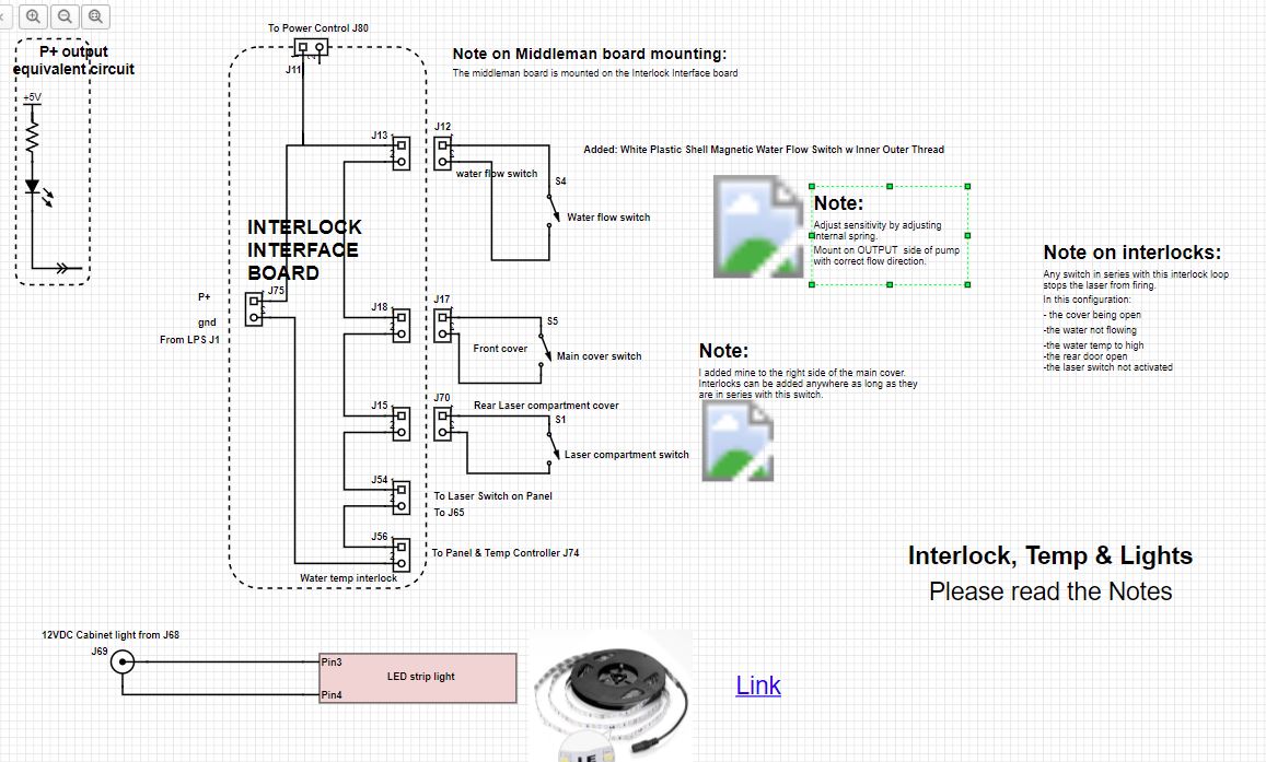
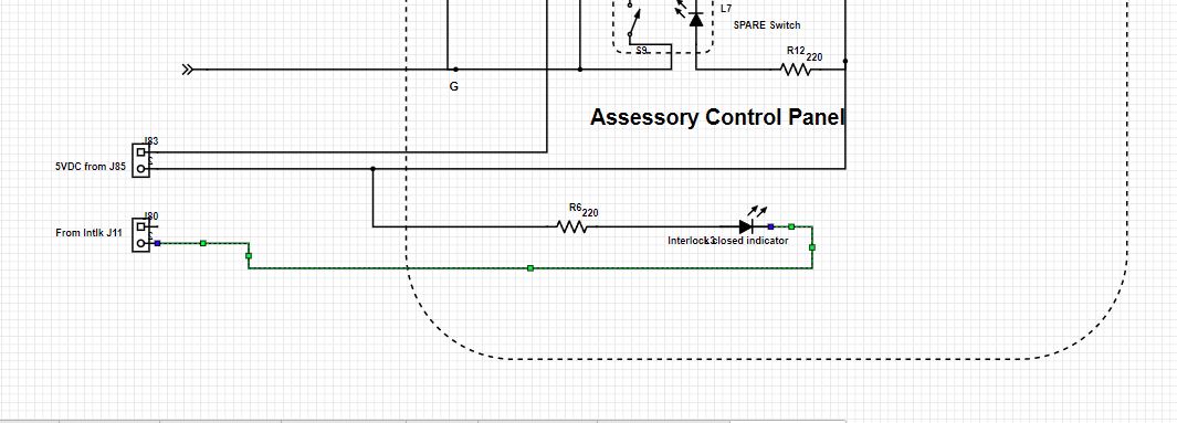
Mine has been running like the attached shem shows for many years…
I also was annoyed by the laser not firing not realizing the interlock circuit was open and this solved that annoyance.
I have thought about instrumenting the interlock circuit and other sensors many times and it never found its way to the top of my list.
Note that J11 just connects the LED on the panel.
3 Likes
Thanks for the schematic. I skipped the K40 step, went to the ‘China Blue’ type. I still have a ‘hankering’ to pick one up. It’s nice to get a clear explanation.
Thanks again
1 Like
@jkwilborn what’s the safety switch setup on a stock K50/big blue? As you can see from Don’s post, he’s added switches for the K40 main lid, laser lid, water temp and water flow. From what I’ve seen, the ‘factory’ upgraded K40’s known as the K40D usually only have a water flow switch. What do the K50’s come with?
I thought they only had the lid switch and water flow switch. And IIRC a key to lock out the front panel controls. Any other?
The door sensor is disabled in the controller firmware and the orginal flow switch has been removed.
I have a 5202 chiller. It senses more conditions than just the water flow. It’s output is wired to the original water flow switch wires. It just pulls it low indicating active, if it goes high, then the lasers halts.
I don’t know what an IIRC is, but I don’t lock out the control panel.
What kind of machine do you have?
1 Like
Proper chiller should cover the water flow/temp events for sure.
IIRC = If I Remember Correctly
I have a K40 and the shop has a couple of Ruida based K50 types which I believe have the door switch, flow switch and lock-out key. They are in a member shop and one of the members broke his K50 tube when the flow switch failed in the closed position.
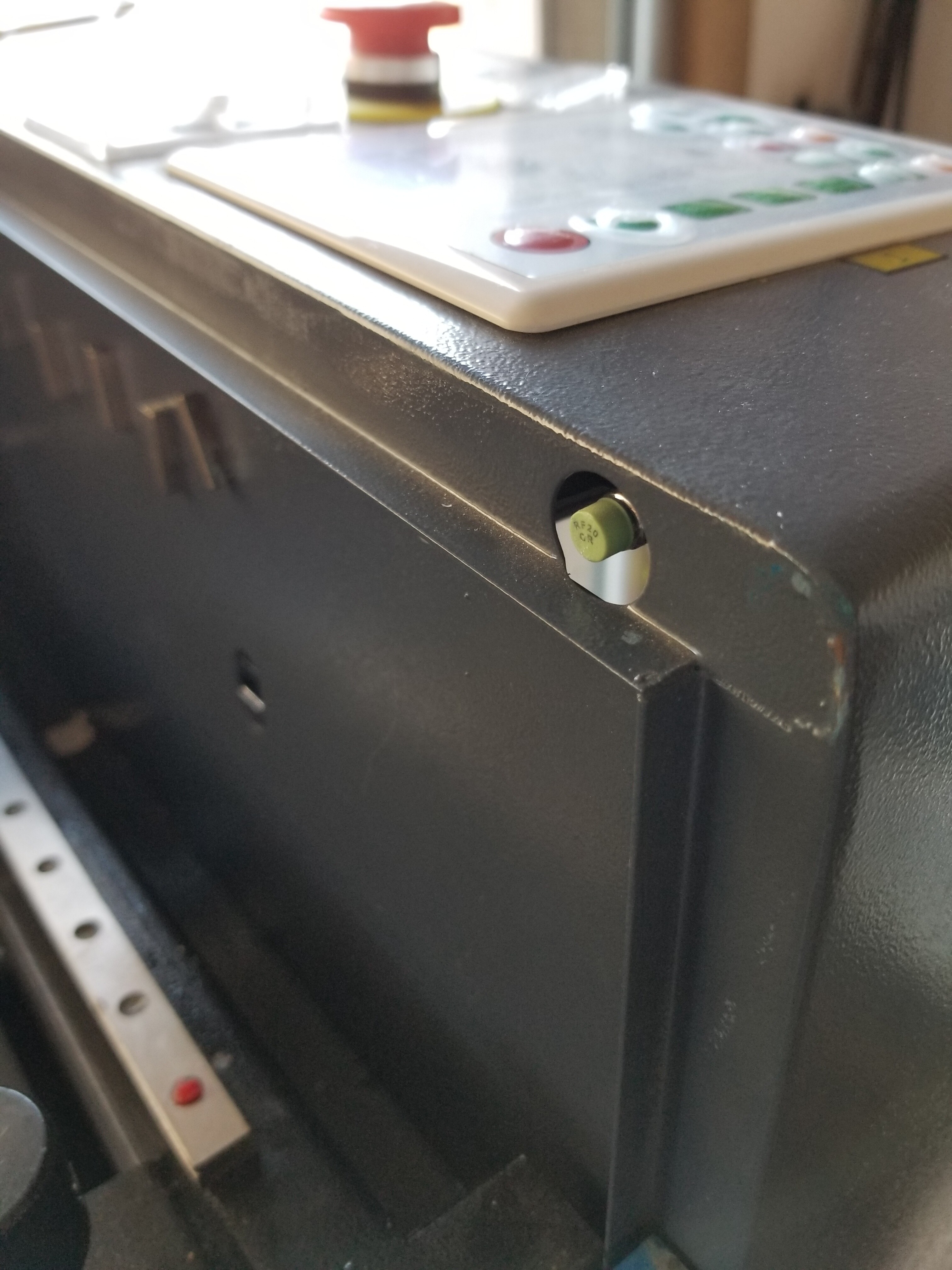
I don’t have any door switches, my laser bay door can’t be opened without pulling the laser out 6-8" and I don’t have a flow switch but instead of a visible flow rotor with a temp sensor. I did purchase the temp monitor with relays Don posted. I very carefully align things with my one good eye.  No burned skin yet. Knock on wood.