Was not going to do this exercise,

Was not going to do this exercise, but saw yet another repetition of “plastic bearings do not work” (and one too many).

Our desktop FDM printers bear light loads and move fairly slowly, compared to the more demanding world of machine tools. We do need precision, but are otherwise undemanding of bearing design.

The (otherwise interesting) video at the point in question:

At this point, was more(!) than a bit annoyed, as the design offered is not suited for making with a 3D FDM printer. We should use designs suited to the materials and method of manufacture.

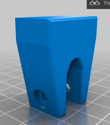
Posted an example Y motion bearing to Thingiverse, with link to the design in OnShape. The example is not meant to fit any specific printer.

I am not inventing anything, here. These are old ideas from examples I saw very long ago (though probably not made of plastic). Too far back to recall the source.

Most 3D FDM printers are simply not accurate enough to fabricate bearings that call for close tolerance. But you can achieve close tolerance in the end with careful design.

There are two design tricks here.

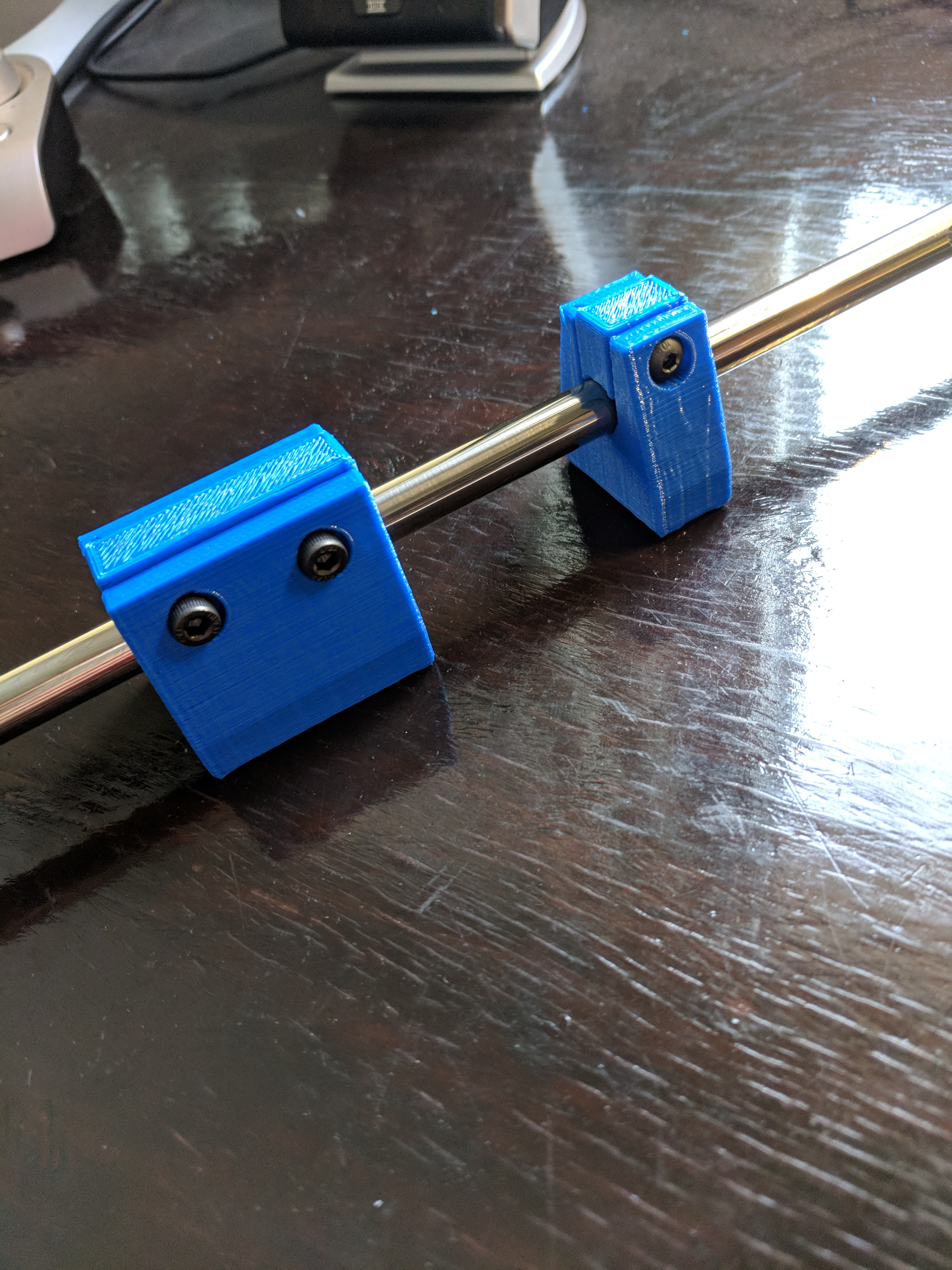
First, there are three lines of contact along the rod. Three points is sufficient to force exact placement of the rod within the bearing. As the two upper points are offset, the weight of the build plate is also forcing exact placement.

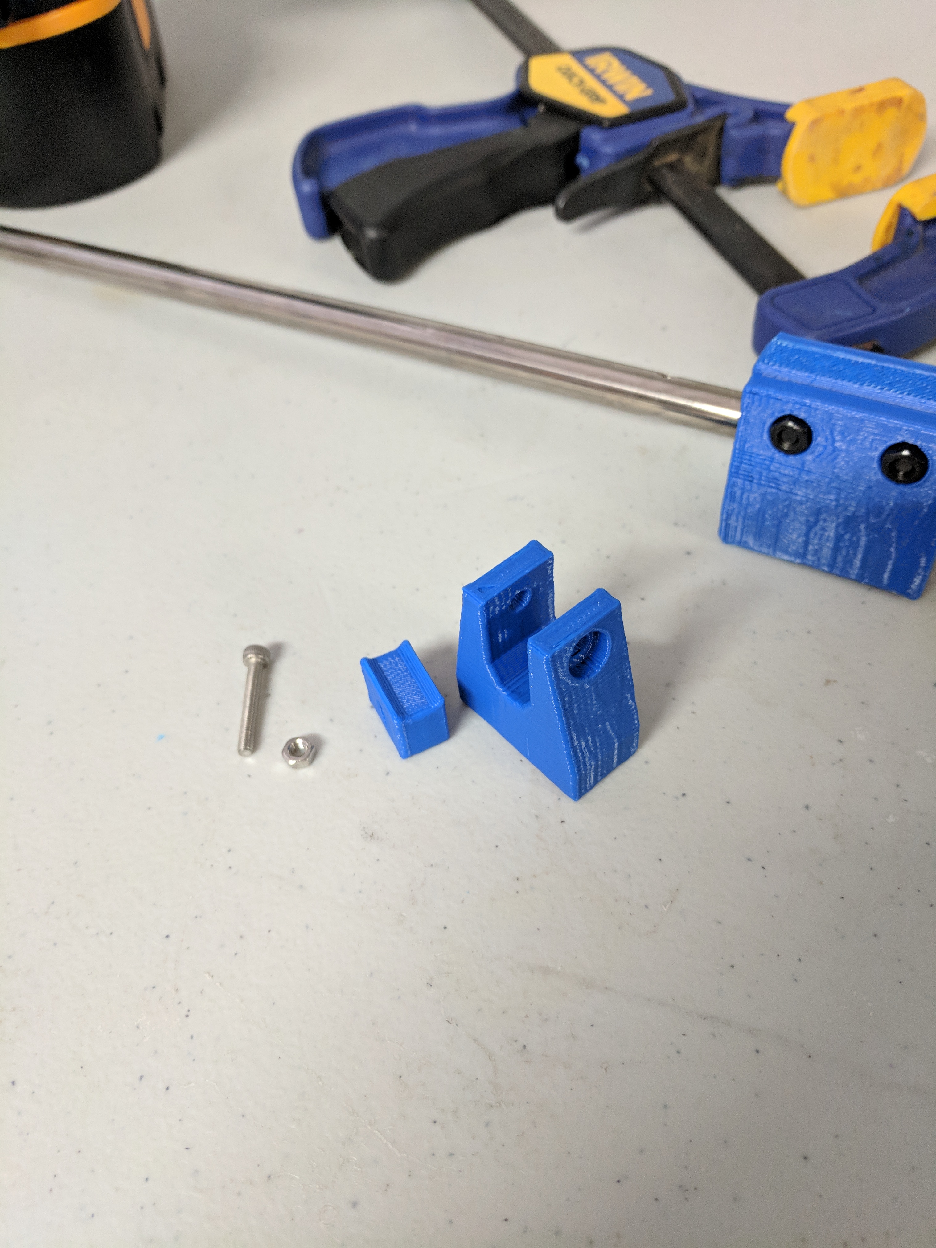
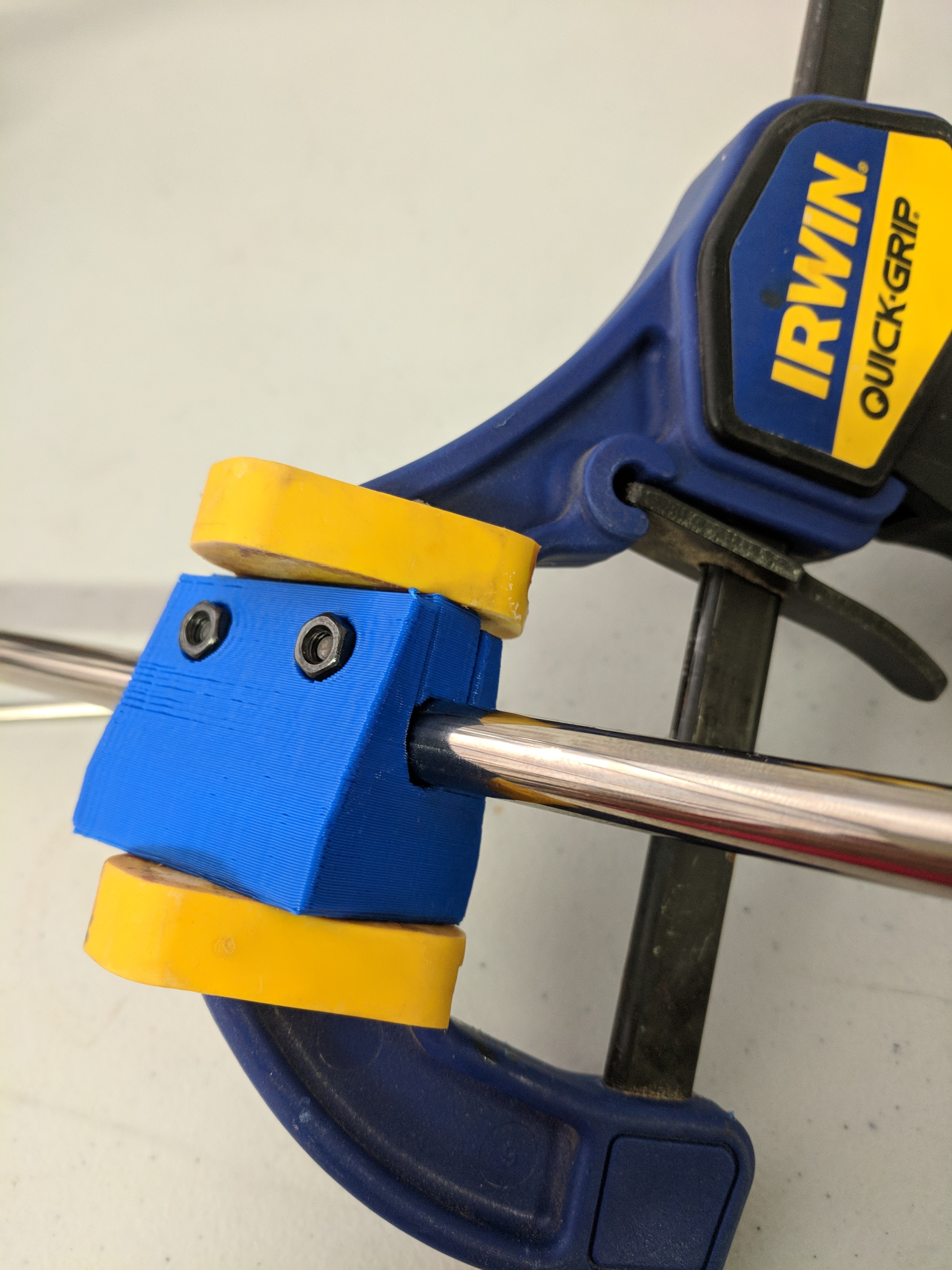
Second, the slot/plug in the bottom allows fabrication with less precision. When assembled, a hand clamp (or any substantial weight) forces the plug tightly against the rod. The bolt locks the plug in place, but does not press against the rod. This is how we achieve very tight tolerances, when our method of fabrication is less precise.

Note the design is for a 10mm rod. The test rod (savaged from an old printer) is actually 9.5mm. The bearing works fine as it is tolerant of small difference in dimension.

I soaked these in a light spray oil (something generic from the local hardware store, that also claims to contain Teflon and Silicone). The slightly porous nature of FDM prints is of advantage, in this case.

Tried both longer and shorter variants. The longer had more static friction, and I do not see any advantage, so uploaded only the shorter. There is no detectable “play” at all in this bearing, and it slides with little effort.

That phrase should be amended to “plastic bearings do not work + worth a shit”.

The static friction of plastic bearings is what really makes them bad. Once moving, the friction isn’t that great but when stopped - it takes a bit to get them moving initially.

My first printer actually used plastic PLA bushings there for a while - until about 3 months later when they started warping, losing shape due to the load, and causing problems with my printer that were hard to diagnose.

Nylon might work.
The lulzbot printers use igus bearings.

The first repraps used PLA bearings. But when the price of lm8uu bearings dropped, everyone switched.

Igus bearings are ok, but because the load is only in one direction they wear unevenly. We have some igus bearing e3d titan extruders and they are worn in lopsided and loose.

Linear rails are much better. Less play and friction, and more even wearing.

PLA is an atrocious bearing material because it creeps under sustained load at room temp. Also it softens and gets sticky if friction heats it up.

ABS is ok. It has fairly low friction on polished steel.

Nylon is a pretty good bearing material. The specific nylon blend matters a bit in theory but I haven’t seen data.

Igus has a tribomaterial filament that should work very well. One key point for igus bearings is that they need to run on a slightly rough surface (like anodized aluminum) to work properly. Smooth linear rods will wear them faster.

Delrin is an ideal material for printed bearings but it’s hard to print because it’s semicrystalline=warpy.

A lot of the historical problem is people using bad designs for the material. Sliding bearing performance is all about PRESSURE. A big contact area will last a long time with low wear. A tiny little contact patch will wear a lot faster. Printing a drop-in replacement for LM8UUs on 8mm rods isn’t a great idea because that concentrates load over a relatively small area. Having preload too high or a design that wrenches on bearings (like cantilevered Z) with sliding bearings is also a killer.

Oil-soaking printed bearings is also a good practice. (Not for igus materials but for everything else.)

I have a bet, unproven, which is why I did not want to write this.

My bet that plain printed PLA is sufficient. I do have plain bearing PLA in service as an X sliders, which work well and show no signs of wear (or creep) or play after a several hundred hours of printing. I suspect the load is so light we are on the part of the curve where things change very slowly.

Not proof, but a hint.

As designed, if the bearings do develop play, I can re-clamp, and continue for a few more years, perhaps. That is not bad. If the bearings do finally wear out, I can print new.

Our predecessors used much less fancy materials, and some of their machines have survived into the present, when load was light and the bearing was on low on the very-nonlinear wear curve.

Started to type “oil soaked wood” and Google auto-completed “bearings” … and I have not tried that search before. :slight_smile:

PLA in service as Y sliders in a moving-bed design carries more load, so that is a concern. Still, I suspect we are low on the curve.

If you have examples of plastic bearings that failed, then I want to see the designs. My guess is I will not like the designs. :slight_smile:

If there was a way to slightly rotate the bearing in their housing every once in a while for a more uniform wear and there was an adjustable tension mechanism then, with a good enough mesh leveling routine one could get decent results. Many applications don’t require very tight tolerances and even the machines that deliver close tolerances, if the application has very high tolerances requirement then some post-processing machining might be needed (lathe/etc).

@Ryan_Carlyle They have more than one -
https://www.igus.com/3d-print-material/3d-print-material

@Florian_Ford If you look closely, the bearing surface is a rounded triangle, not circular. With the clamp this allows for off-spec rods, and any wear, with no further design adjustments needed.

This is also what nets us a zero-tolerance end result, when the tolerance of our printers is relatively crude. Old tech, re-used.

BTW, printed the test bearings with 0.3 x 0.4mm layers at 60mm/s with 20% infill - so absolutely no attempt at unusual precision or strength.

If you are going to do printed bearings, why not printed rods to go with them? You might even do printed linear rails.

@Baldur_Norddahl Plastic on plastic is WAY higher friction than plastic on polished steel. You’d probably want to print wheels at that point.

@Ryan_Carlyle However, oiled plastic sliding on anodized Aluminum is not bad. Kind of what @Baldur_Norddahl suggests, but not. :slight_smile:

I guess one can do rolling plastic on plastic for light duty jobs like laser cutting just as steel on stell is a too high friction while rolling steel on smooth steel works. Maybe no the best expl but u get the idea.

@Ryan_Carlyle yes what about using wheels? Several successful printers do that, but on aluminium extrusions. Instead you could have plastic wheels on plastic rails for a fully printed solution. You could also do printed plastic ball screws or plastic linear bearings (the kind with balls inside).

@Baldur_Norddahl you"d have to have plastic that has metal properties… kinda. Plastic leadscrew already exist in a printer… FischerTechnic or something …

@Baldur_Norddahl yeah, plastic cylindrical rollers on a printed surface is a viable option. You could even use lengths of filament as rollers, if you wanted. Balls are too hard to make and have too little contact area to survive long. Cylinders have much more rolling surface area so the contact pressures are lower.

@Ryan_Carlyle but plastic as a linear guide would need some support of sorts, it will deform and the elastic deformation of plastic is bad, hence the ‘plastic’ name… And if you support a plastic linear rail with something as linear, presumably metal, the only reason of doing this would be plastic rolling on plastic wearing much less than plastic rolling on the supporting metal directly?

@Florian_Ford look at the Snappy RepRap with big printed beam like structures. Or any plastic-frame printer, really. If you design a good beam or truss type structure, or make a torsion box with plastic sheets/webs, you can achieve high rigidity with plastic. Then just run plastic rollers of some kind directly on the plastic frame.

It’s very doable, but will the print quality be good enough to self-replicate? That’s always the hard part with extreme RepRap designs.

I never liked the idea of a completely 3d printed 3d printer besides the novelty aspect. Some designs have worked in the past, but a saw, a drill, and some wood/metal goes a long way in improving quality. The cost is negligible and materials are plentiful.

A good design can use all available materials at a low cost and still be high quality. Proper use of the materials can go a long way. You need to understand the properties and test the limits of the materials. Personally I strive for high accuracy and reliability I think that skimping on bearings to save $20 on a printer isn’t worth the sacrifice or potential compromise. It doesn’t mean it isn’t possible - there are some cool printed bearings that utilize igus filament simply placed in tracks, but looking at the cost and availability of the material just doesn’t justify it.

@Stephanie_A reprapping is fun for the engineering challenge, and has some potential benefits for remote applications. It still has the challenge of how to make more filament though!

You folk are getting far too carried away. :slight_smile:

Aluminum extrusion is strong, precise, and inexpensive. Printing a plastic equivalent does not make sense, at least to my mind.