Hello. I purchased a CO-Z Motorized TV lift off of Amazon and one of the reviews, the guy states that he was able to put in a wifi module that enabled him to utilize his Amazon Echo to activate the lift. I would like to replicate his efforts, but I don’t know squat about circuits and relays and switches and such. I was able to get a wifi module with a 2-channel relay to power a motor and get it to spin in both directions but I don’t know enough about where to connect into the existing board. I know enough to get into trouble, but not enough to get me out. Any assistance would be greatly appreciated.
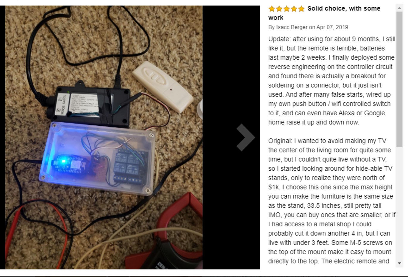
This is a screen shot of the gentleman’s post on Amazon. I noticed his is using a 4-channel relay board, and a wifi module separately. The wifi module I used was a 2-channel relay and wifi built into one.
From the amazon customer pictures, it looks to me like the lift is being driven by simulating the PB in the lift control using an ESP32 controller. Like # 3 below.
Update: after looking at other offers of the lift on amazon it looks like the control panel is separate from the controller. Therefore I think this hack I think the control panel was replaced with an arduino+relay module to simulate the panel.
I would start by finding out how the motors and sensors in the unit are wired and draw a schematic of the units interface with the controller. It will be interesting to see if the unit has end stop sensors.
Also, open the controller and find out if you can get to the up/down functions initiated at the control panel. Update: This may require finding out how the control panel is wired to the controller.
A user manual will tell us how the up/down functions work.
Then you can decide how to interface with the unit.
Approaches: 1. Hack the existing controller: if you can get to the up/down control (PB) this may be the easiest way. You can simulate PB contacts closing with the inching function on the wifi relay module. This lets the controller do all the motor and end-stop management.
2. Build your own open-loop Google Home compatible controller:
There are many inching controllers (timed relay) that can be configured to turn on a motor for a period of time [modules like you already have]. This assumes that the lift repeatably reaches its endpoint in the programmed time.
The challenge with this approach is that if the lift is not repeatable in its movement you can over/underdrive the motors when the unit gets to the stop. I tried an open-loop approach with a shade controller and it was not accurate enough without end stops.
I have been working (causally) on a shade controller that uses an inching relay as the front end to process the Google voice commands and starts an Arduino to control the up-down of the motors and end-stop recognition. This allows a closed-loop design with cheap voice recognition (no google interface programming). I can share it if you are interested.
The other annoying element of this approach is that in Goole home you have to set up a device with two channels one for up and one for down.
Build your own ESP32 controller:
Much more complicated, but a wifi-based controller could be built that interfaces with IFTT and that in turn with Google Home. This would still need the device control from #2 but would be a cleaner Google home interface.
You would need a cloud service to manage the device and an IFTT account.
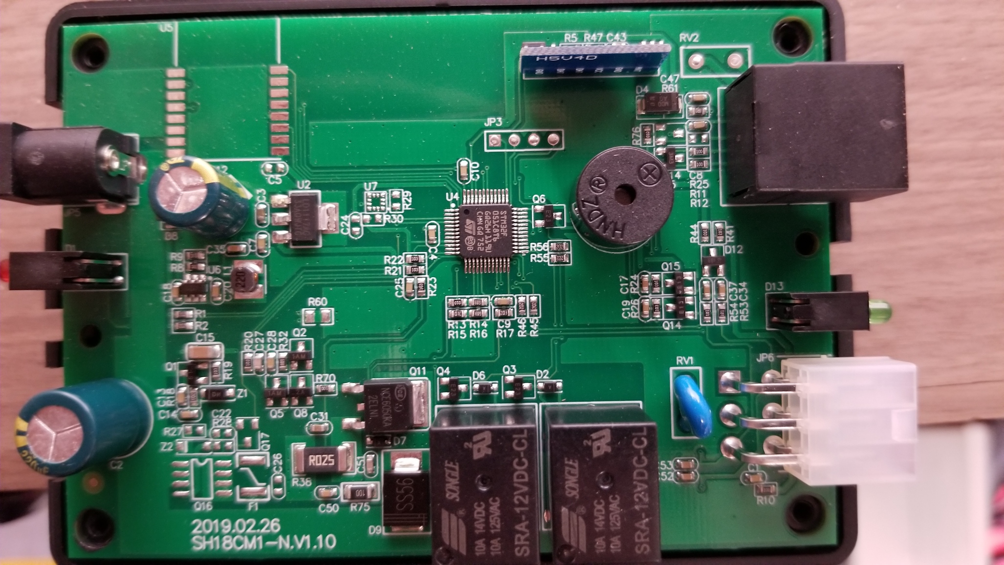
Thank you for the info. I think I’ll try and see what’s behind door number 1. I think I can find what pins control the up and down. The unit (as with most things from China these days) did not come with any user manual. The device setup is pretty straight forward. All of the wiring goes into one control box. There is a control panel that is attached to the main box via CAT5 cable. Here’s a picture of the control board.
The left side is just the power supply. The right side top with the CAT5 goes to the control panel. The bottom right six pin connector goes to the lift. I haven’t tried to get into the lift yet as its pretty sealed up. The unit also came with a remote control, but I haven’t tried it yet. I’m assuming the receiver is on the control panel. The control panel has up and down buttons as well as four buttons that you can program for up or down. You set the desired height using the up and down arrows, then program one of the four numbered buttons to go to that set height.
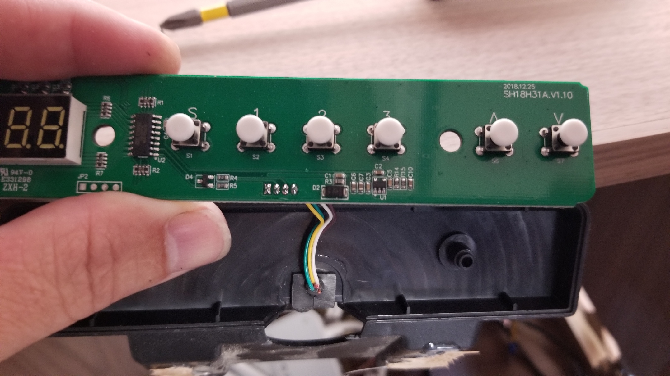
This is the control panel. The two buttons on the right control the up and down.
The one on the far left labeled “S” is the SAVE button. When you get the lift to whatever setting you want, you push the S and the corresponding number 1, 2, or 3, and it’ll save it to that spot. The 1, 2, or 3 is just whatever you want.
The control panel has 6 switches yet there are only 4 wires going to the controller and it looks like one of those wires is grnd and maybe another is VCC.So it may be that the control panel to controller interface may use some kind of encoding?
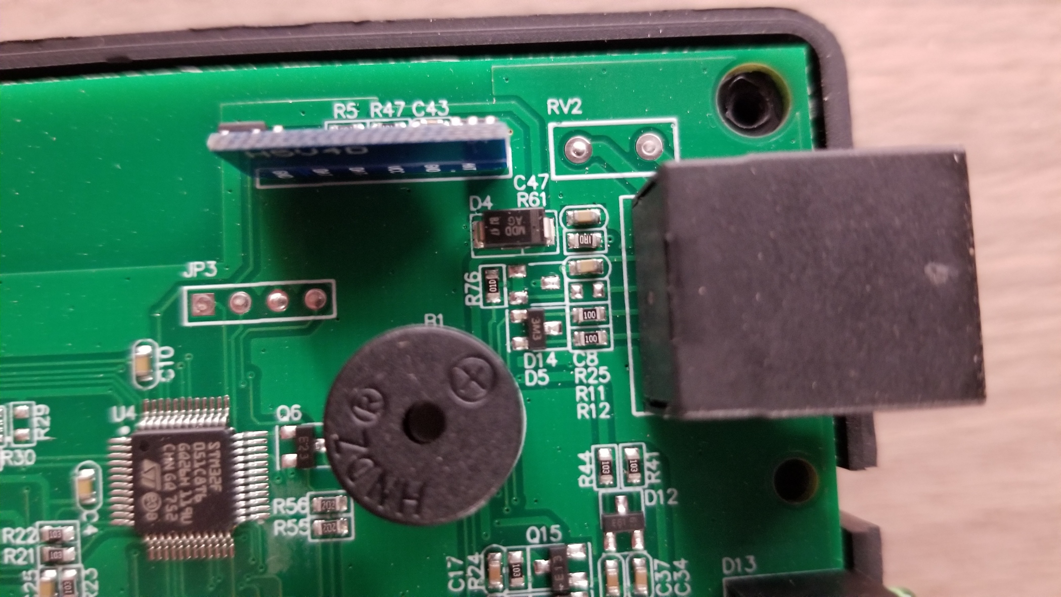
Post picture of the 16 pin IC that is on the control panel (part #).
Contact the guy who did this on the amazon reviews and see if he will share how he interfaced with the controller.
otherwise …
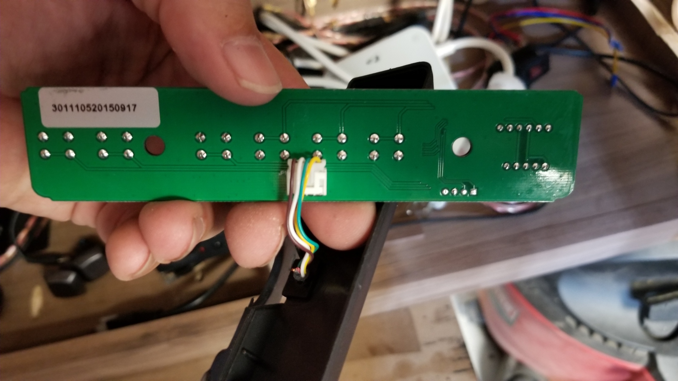
On the control panel trace the circuit from the switches (6) to the control panels 4 pin connector.
On the controller trace the circuit from the 4 used pins on the CAT5 cable to their endpoint
Just had a thought. The push buttons on the control panel number 1-3 are just buttons. What if I were to tie into them in series and install a wifi module that is essentially a switch like this one:
That would fool the control board into thinking the button was pushed and would initiate the lift. Those little wifi switches just complete the circuit like the push button.
Button 1 is full up and button 2 is full down.
Just a thought?
I reached out to the guy on Amazon, I doubt he will say anything back. there have been three other replies to his review asking him to clarify his process.
Update. I didn’t use the ESP8266 like the link I posted, I used the 2-channel wifi inching module and set it for 0.5 seconds. I found out which pins on the control board the button connected, and wired into that, then into the wifi inching module. works great and it keeps the memory setting. So essentially the wifi module is “pushing the button.”