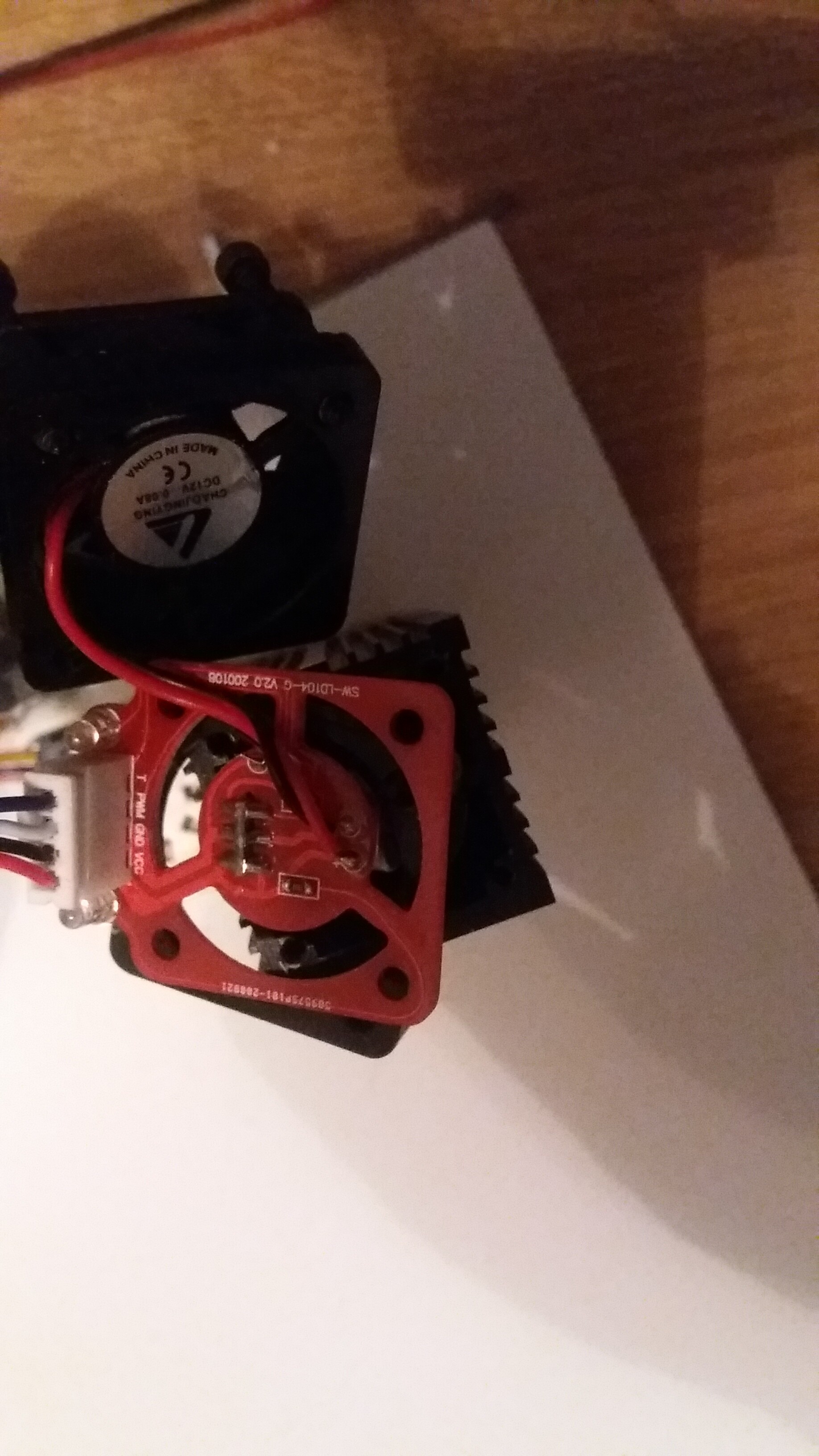
VCC GND PWM T
T stands for TTL I believe.
First three cables go together into a plug, and the fourth (the T) goes to another one as a single cable.
VCC: 12V for the laser diode?
YES 12V for the laser diode
GND: gnd of the driving source
Ground for the laser diode. I think it is common for PWM and T. We use or refer to the fourth line as ground.
PWM: a digital stream of pulses whose period of on is proportional to the needed power. IE: for 50% power the pulse is on for 50% of its period. From the label, I would say high true.
PWM input for power adjustment
T: a high true laser enable signal?
TTL input for 100% power without PWM.
Some laser units have 3-pin VCC, GND, PWM/TTL with a PWN ON/OFF button. with common ground. And as you see from the pictres three lines are left with one common ground and one (T =? TTL) is left alone.
So for control, I think we should use the common GND, and either PWM or T (full +5V, or True HIGH as you call it?), depending on the choice.
During my very first try outside the unit on my cnc, I applied +5V to PWM and ground to T from Arduino Nano, and it worked. +5V turned the diode ON, and 0V turned OFF.
I have found that electronics coming from Asia often do not have the signal polarity included in the name such as T (high true) or -T (Low true). Therefore the label may be misleading.
What are you trying to control the laser with? A controller that came with the machine or a DIY one?
There is a built-in driver on the laser unit. Under the fan, inside the temperature sink. I tried to get an image, but of course could not pull them all out. I just send +5V to enable the laser.
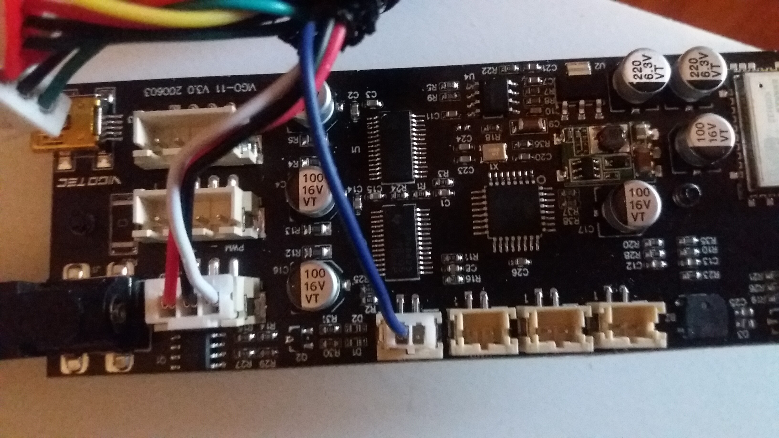
I tried controlling the module by connecting +5V to PWM pin, and GND to T from various sources: From an outside 5V DC adapter with or without common ground with 12V+ (VCC), or Arduino Nano +5V and GND, but did not work ( It did in the very early first tests I mentioned in my previous message).
I measured the voltage between PWM and T: -2.3 V. Yes, MINUS 2.3 V. Tried several times. Yes, correct. MINUS.
I doubt this measurement is meaningful as my guess is that these are both inputs. Which signal did you have the + meter probe on?
+ was on PWM.
Why I consider this minus as meaningull is due to the change of the overall behaviour of the unit. +5V holds the laser, and in its abscence laser fires. It was vica versa in my initial tests.
So the I tried inputting negative volts. ie, connect ground to PWM and +5V to T. And it works. I mean it controls the laser module. In a negative way of course. If the voltage is on, no laser beam. If off laser lights up.
Guessing: This may mean that PWM and T are low true signals. i.e. when T is low then bringing the PWM low turns on the laser? When T is high PWM has no effect.
I would try combinations of these two signals and see if you can determine the control method.
As I said above, I think we should either use PWM or T, but not both with the main GND.
----Measurement table -----
| T |
PWM |
Laser ON |
| G |
G |
YES |
| 5 |
G |
NO |
| G |
5 |
YES |
| 5 |
5 |
YES |
G= ground
5= 5V
I would also measure each signal input relative to the ground to see what the static state is.
----Measurement table -----
| Signal |
Voltage |
| T |
-2.2 |
| PWM |
0.0 |
| Grnd |
0.0 |
| VCC |
12.0 |
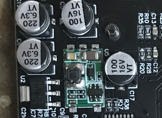
So, somehow the logic on the board was reversed?! And combined with 2.5V but not 5V, can we say that the AC/DC converter is faulty on the board? Positive half gone?
I doubt the board has an AC-DC converter? Isn’t the VCC input a DC value?
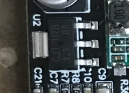
Yes I am sorry. No AC of course. I meant the Voltage Regulator or Voltage Controller as they call it on AtMEGA chips.
This is the content of the devices file on the machine:
Mega(ATMEGA1280);m1280;stk500;57600;
Duemilanove/Nano(ATmega328);m328p;stk500;57600;
Duemilanove/Nano(ATmega168);m168;stk500;19200;
Uno(ATmega328);m328p;stk500;115200;
Mega(ATMEGA2560);atmega2560;stk500v2;115200;