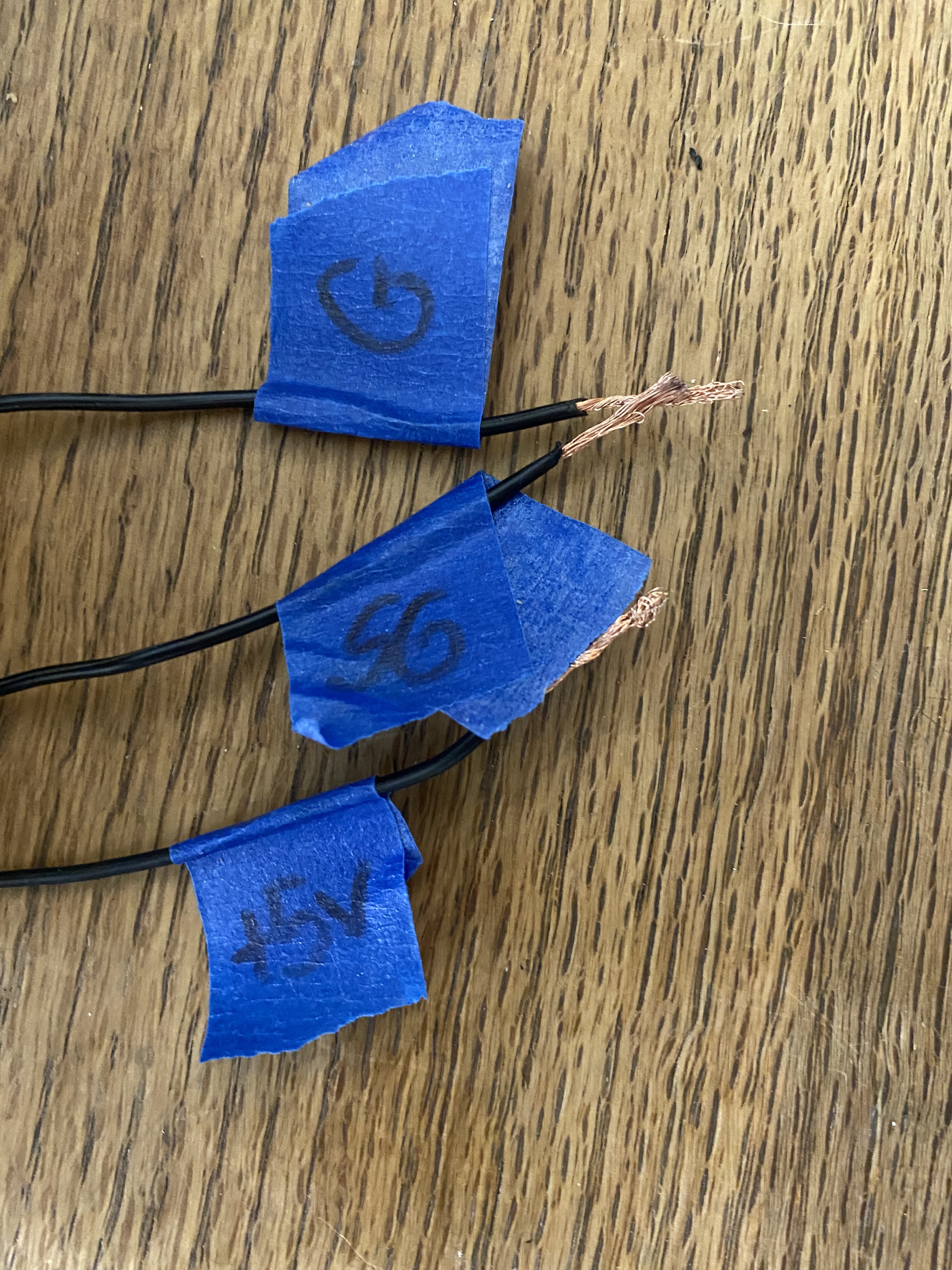
I would use a meter to verify and label the + & - connections on the new supply
Also use the meter to verify its voltage.
On DC the meter should read approx 5v.
On AC the meter should read very low voltage
… be very careful to:
Connect to the nano with the correct polarity.
New Supply +5v to Nano 5V
New Supply Gnd to Nano GND
Insure that the new PS’s ground is connected to the existing grounds
When the New supply is installed and powered up again check the voltage.
If correct plug in the usb and watch that the 5v rail stays solid.
If all that is good you have to solve the driver problem at the PC end before making a connection.
If you get that far come back here for more focussed advice on the driver install.
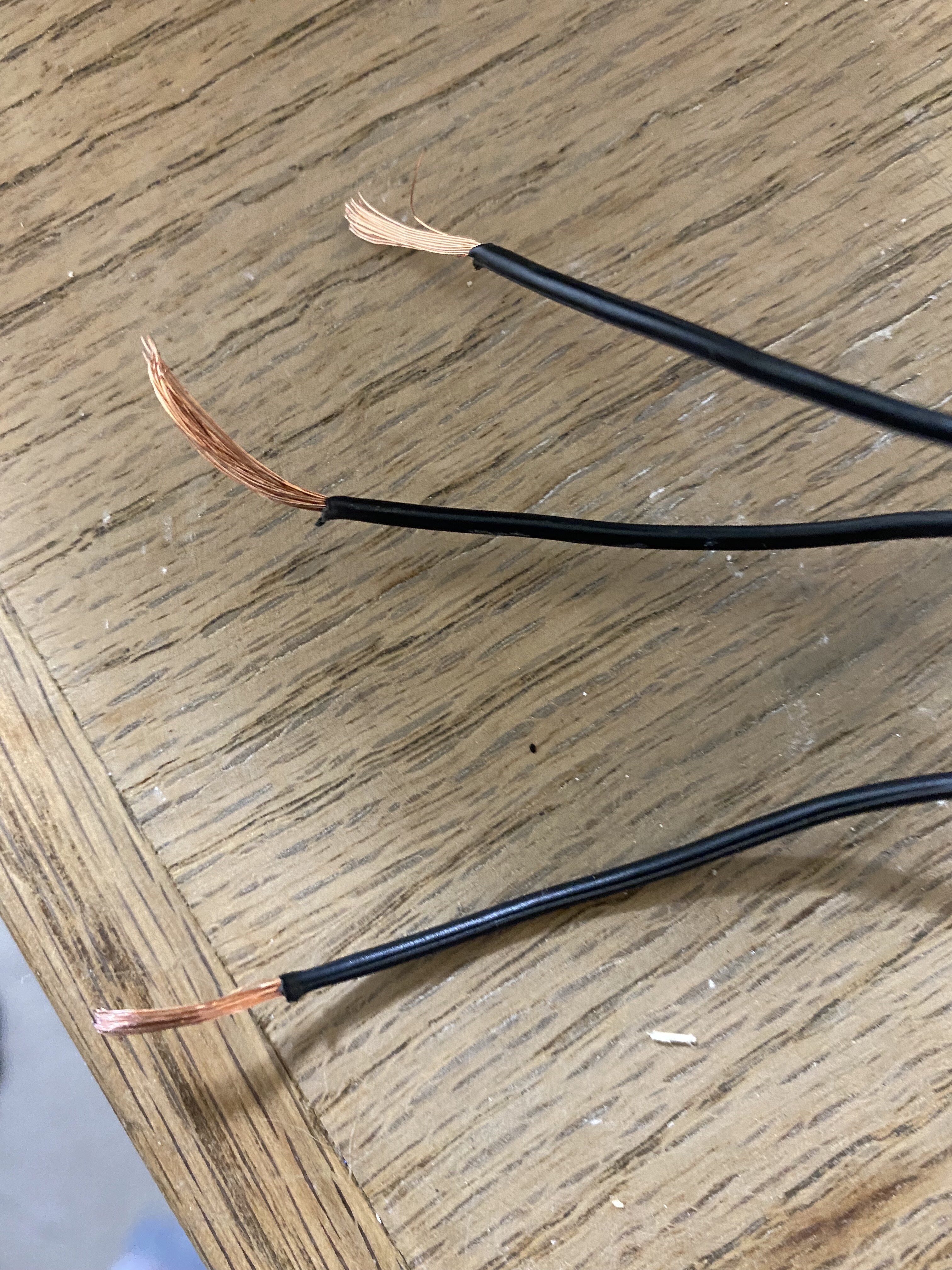
Okay. So the 5v power supply has 3 wires. I’m assuming, they are equivalent to red, black, and a ground on similar power supplies. When I tested the three wires, I get the following (I will use A, B, and C for simplicity):
A to B: 0V
A to C: -5.1V
B to C: 0V
Based on these results, I would assume I want to hook the C wire to the 5V input on the M2 Nano and probably the B wire to ground. Or is it correct to hook the A wire to ground?
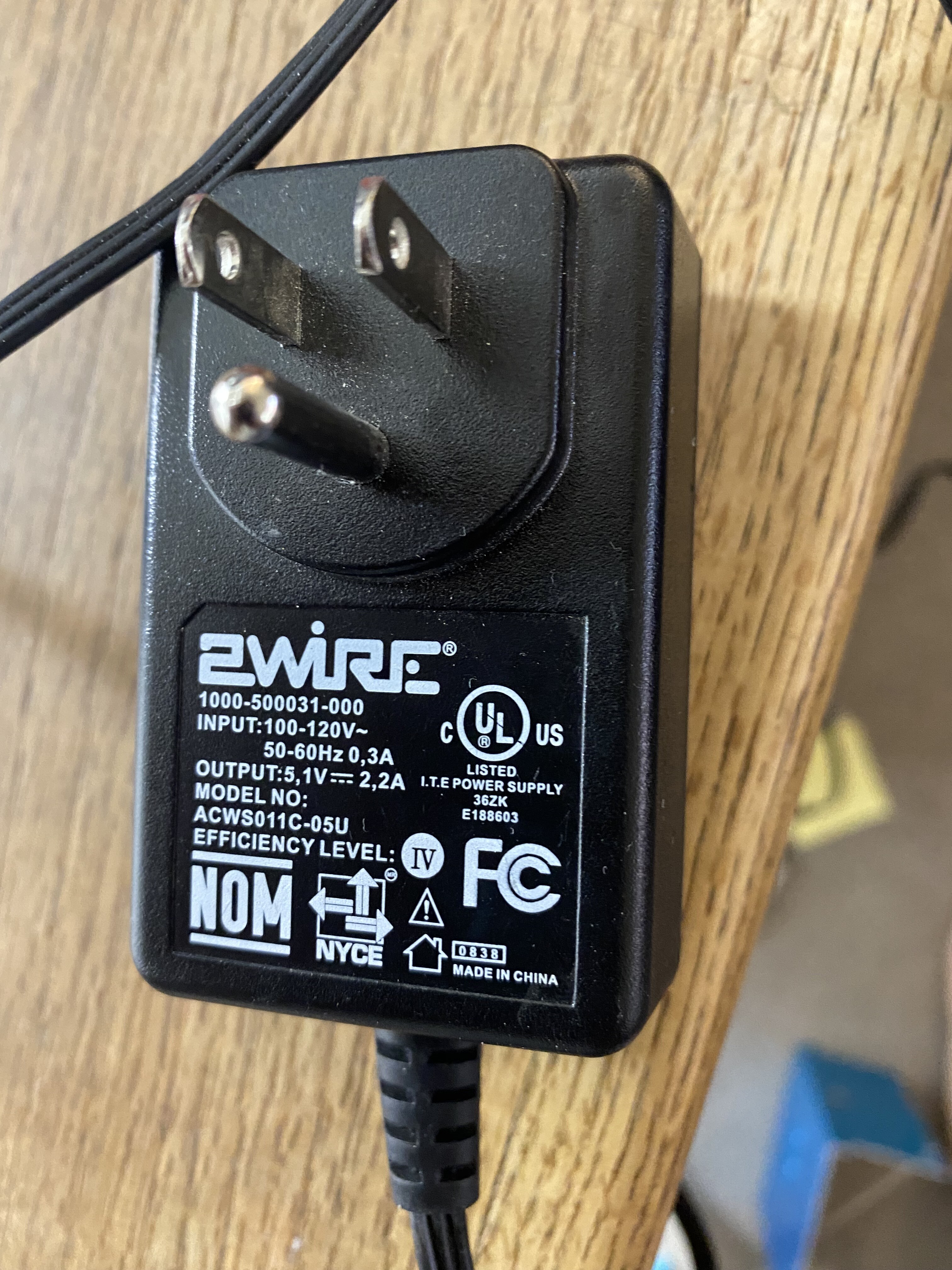
Can you post pictures of the supply one showing its label one other showing its wires and one showing the plug?
Not clear why that brick has 3 wires unless one of them is a safety ground?
Is it a 3 prong plug
What AC voltage are we working with?
Are you in US or other?
If this is a 3 prong connection we may want to verify which of A or B is connected to the ground spade in the connector.
We want the PS ground connected to the Nano’s ground and the safety ground connected to the frame.
I am guessing that you want C (+5V) and A or B (5V Ground). [depends on finding out what A & B do]
I would have included these, but I thought they were implied. Is there a situation where I could have different readings going the opposite direction other than the changing the - to a + or vice versa? I guess for a resistance reading across a diode or transistor, but I’m not sure for voltage drop. Its been 20 years since I’ve studied electrical theory.
Thanks Doug… Sorry about that. I’ve dealt with a few arudino nanos in service with cnc or other automated stuff. I’ll have to look that one up… Thanks again.
This may be an issue as the case ground is connected to the ground of the power supply (i.e. through the connection that goes back to the 110 in the wall). Thats how the machine came wired when I got it. Should I just connect the ground coming from the wall directly to the ground of the power supply (bypassing the connection on the case) and then connect the safety ground on the 5v power supply to the case? Additionally, are there any other wires that should be grounded to the case and not to the wall?
The respective ground connections for the LPS, M2 Nano, Control Panel on top of the machine, 24V external power supply, and 5v power supply are all connected to the bolt on the cabinet of the machine. The same bolt is connected to the wall ground wire that goes to the ground pin on the plug for the entire laser at the back of the machine.
Something happened! I was able to control the laser from Meerk40t! I was a little concerned after I installed the new controller and windows still couldn’t recognize the laser and I couldn’t download the K40 Whisperer drivers, but I tried Meerk40t. Before I even tried to start engraving, I went to the navigation tab, and I wasn’t expecting anything to happen because I had tried that when I first downloaded Meerk40t and it did nothing. When I hit the right arrow, I heard a sound from the laser! It blew my mind. It was so exciting to be able to control the laser from the computer again. I moved all directions though and test fired the laser at the acrylic to ensure it was still working.
I have a little work left to do before I can give it an actual test run of cutting and etching. I have to re-install my air assist that I removed to work on the wiring, tape all my connections, drill holes to mount the power supply firmly to the cabinet, install new LED lights for the inside of the cutting area as they went out when the power supply fried, and reconnect the little laser pointer that showed where the laser was cutting/etching. Thank you all so much for all your help!
Is there any point to trying to get K40 Whisperer to work at this point? I was able to load my svg file from Inkscape into the Meerkt40 program. Will it do everything K40 whisperer does? Or should I eventually try and resolve the driver issues there?
Well I’m not certain on this, because I had the external 5v power supply installed before I received the new M2 Nano. Should I try removing the external 5v power supply to verify the external power supply is required when using a HY-T50?
I definitely have a wiring issue, but luckily I didn’t break anything yet. The laser is showing a % while the switch on the panel is off. I’m going to look at some schematics and possibly retrace all the wires again.
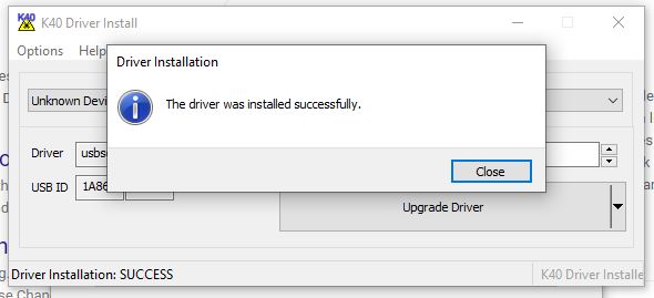
Okay strange. Without changing anything else on my system, I was finally able to install K40 Whisperer drivers. Its nothing short of magic and I wish I could tell someone definitively how I did it in case they wander upon this forum looking for answers.
Glad to hear it’s working but I dumped Windows years ago and one reason was that I don’t like magic.
That whole ‘reboot the computer and it’ll work again’ thing is hideous.