Hi
I want to upgrade the tube in my k40 to a 60w tube, I want to use the old psu to power the motors etc, and was wondering how I would connect the new psu to the old psu
Are you wanting to use the DC from the existing LPS but drive the laser from a new LPS.
i.e. you want to use them both?
I want to use my original psu to drive everything except the laser and the new lps to drive the laser. IE: the old one for the motors etc and the new/black lps for the laser tube.
I guess you could disable (just don’t enable the LPS) the HV part of the LPS and just use the 24V.
Just to be safe I would remove the HV lead.
I would advise just getting a separate supply the stock one is marginal anyway.
Is the nano using the 5V?
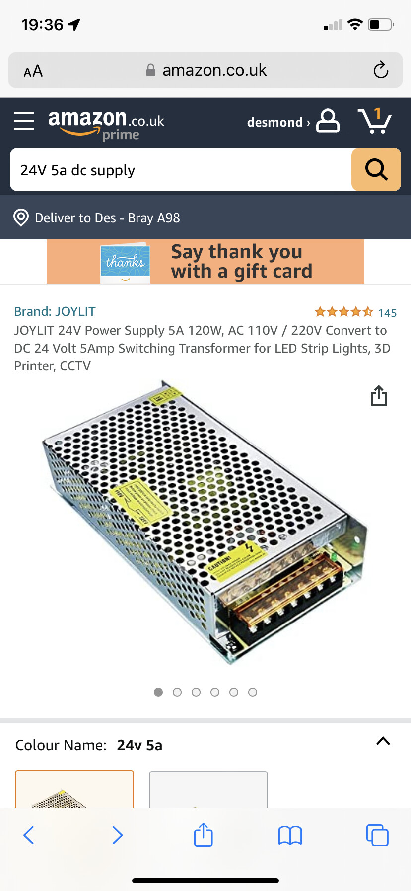
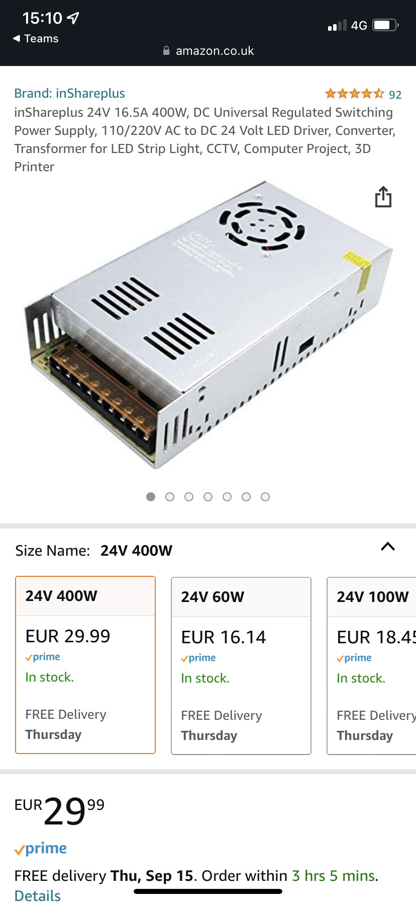
This one would do it all and give you 12V for accessories: Kit
Hi, if I got the psu you have linked, would there be a wiring diagram available anywhere?
We probably can whip one up.
Post picture of:
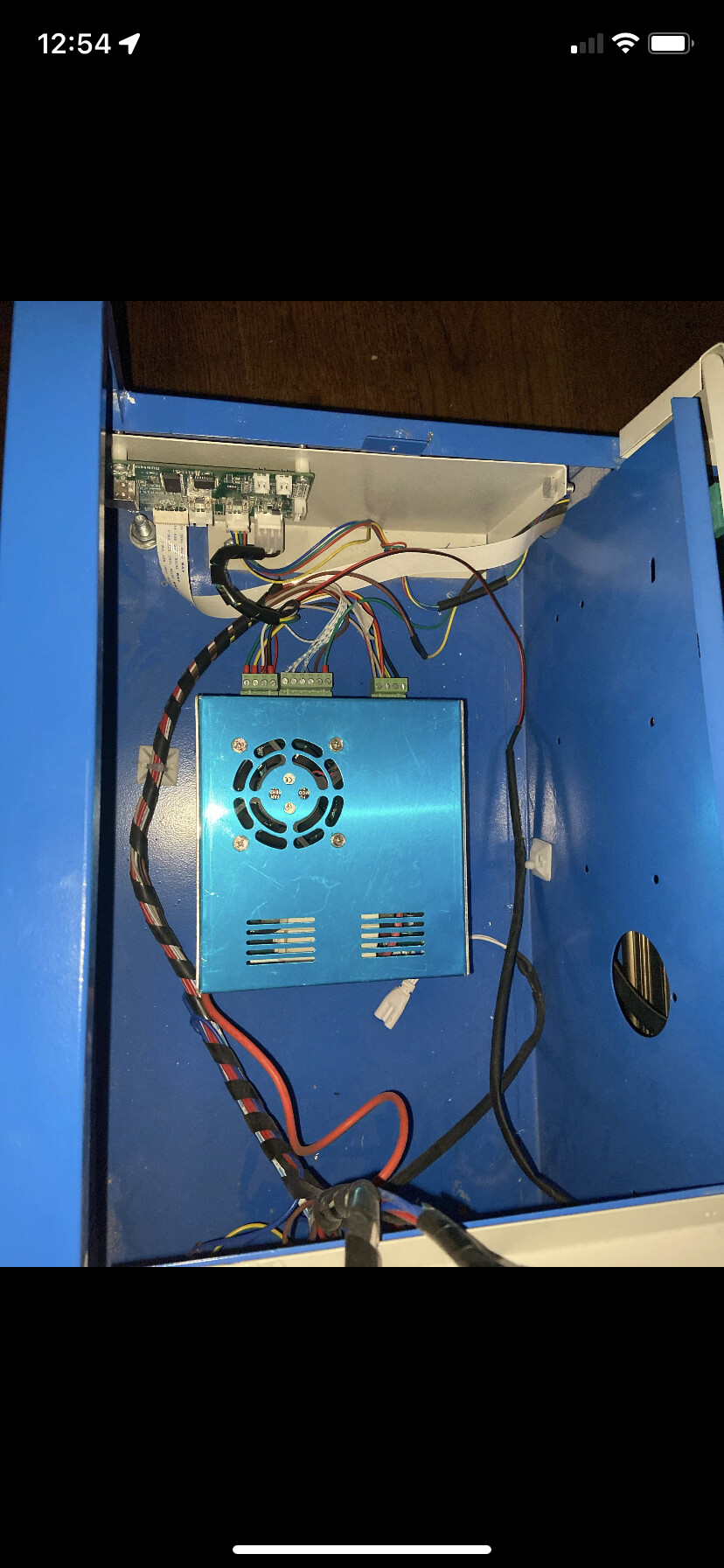
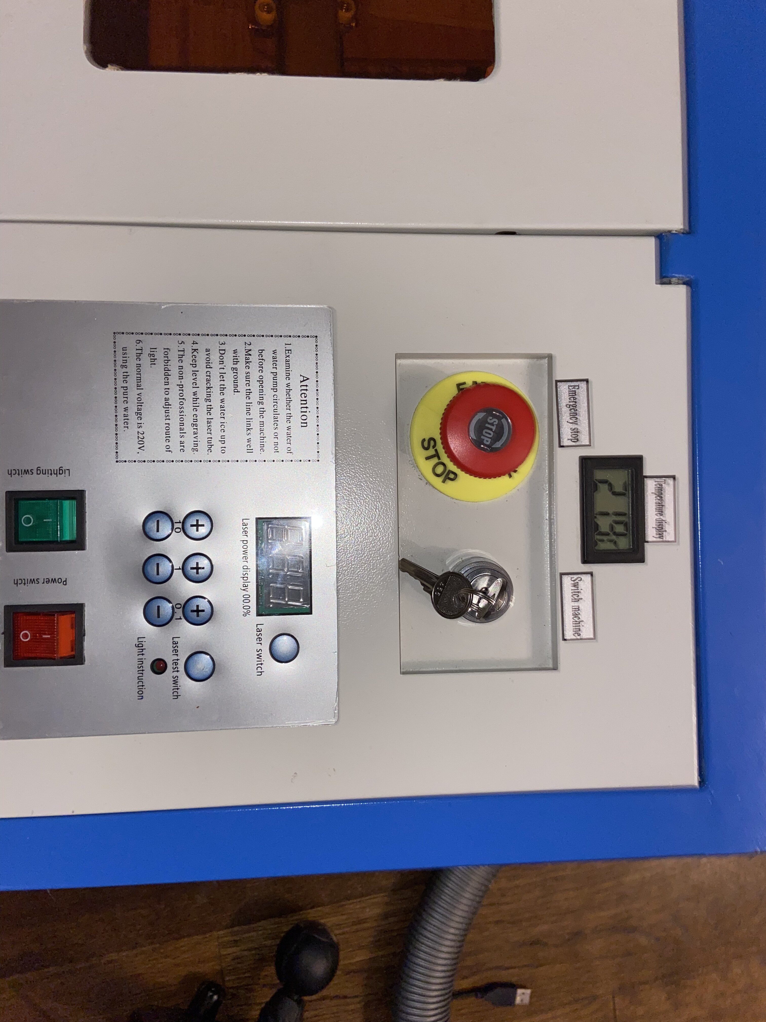
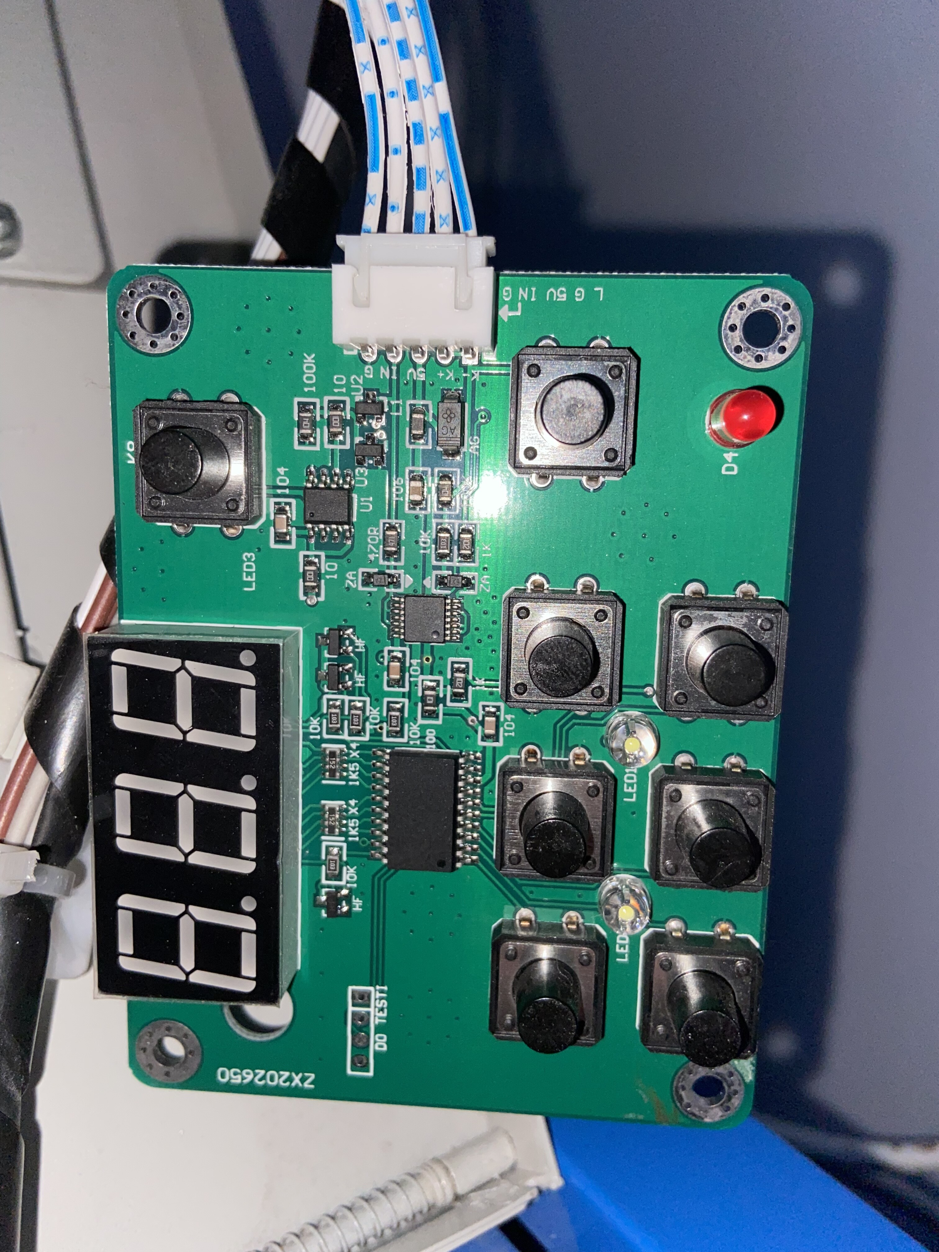
Control panel front and back
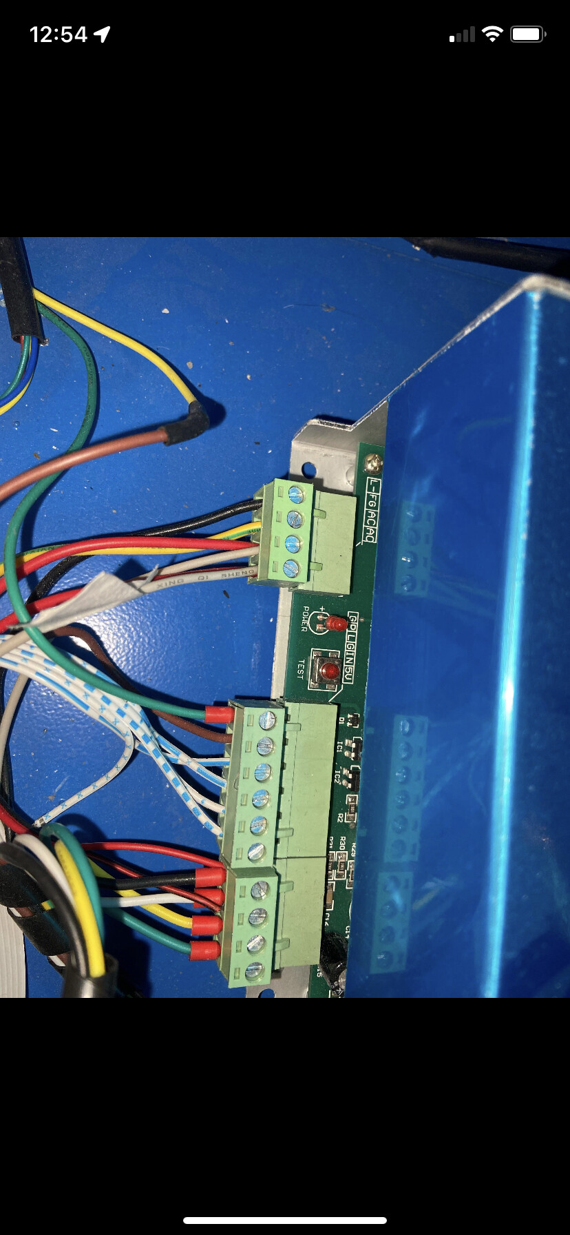
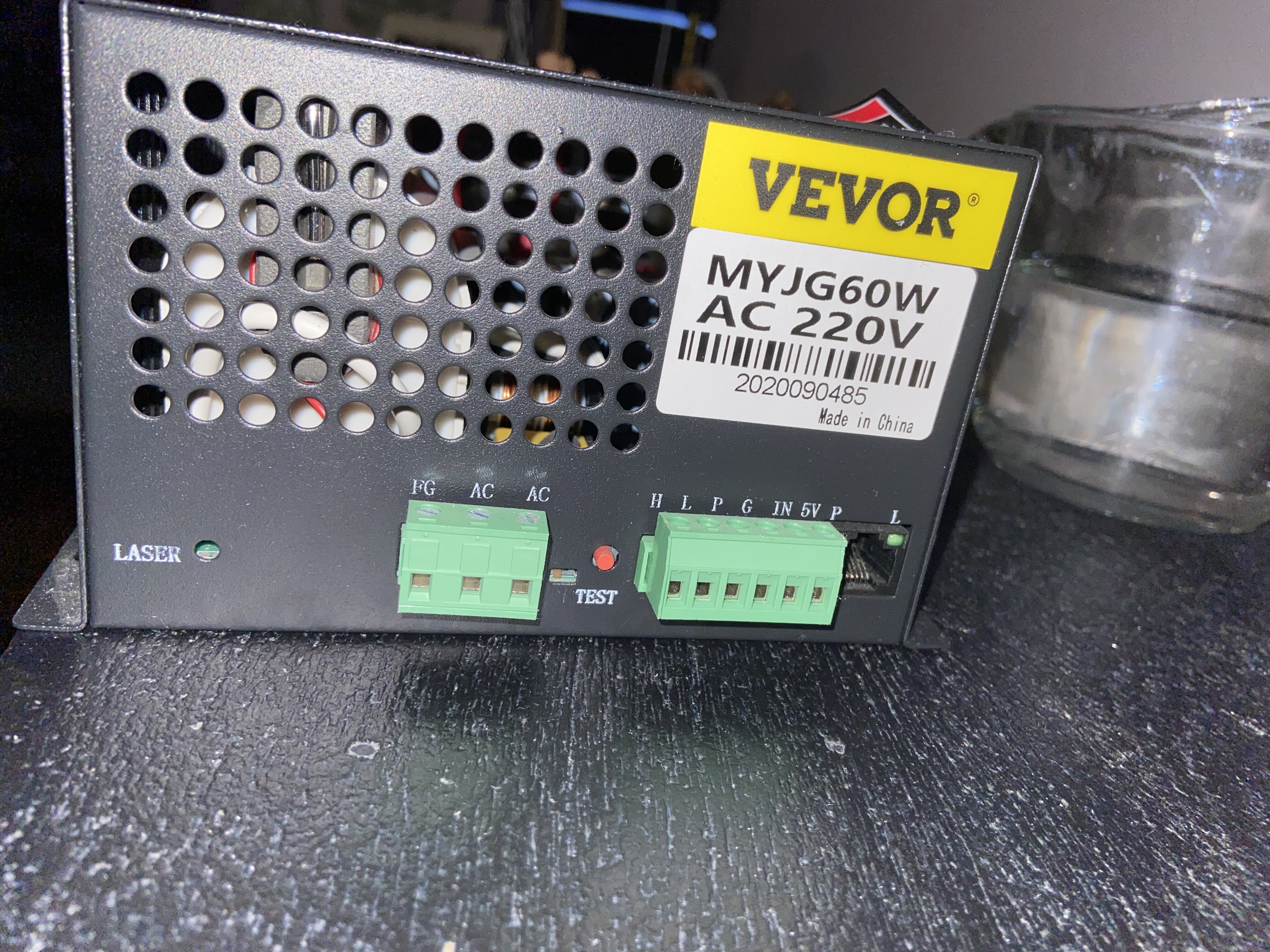
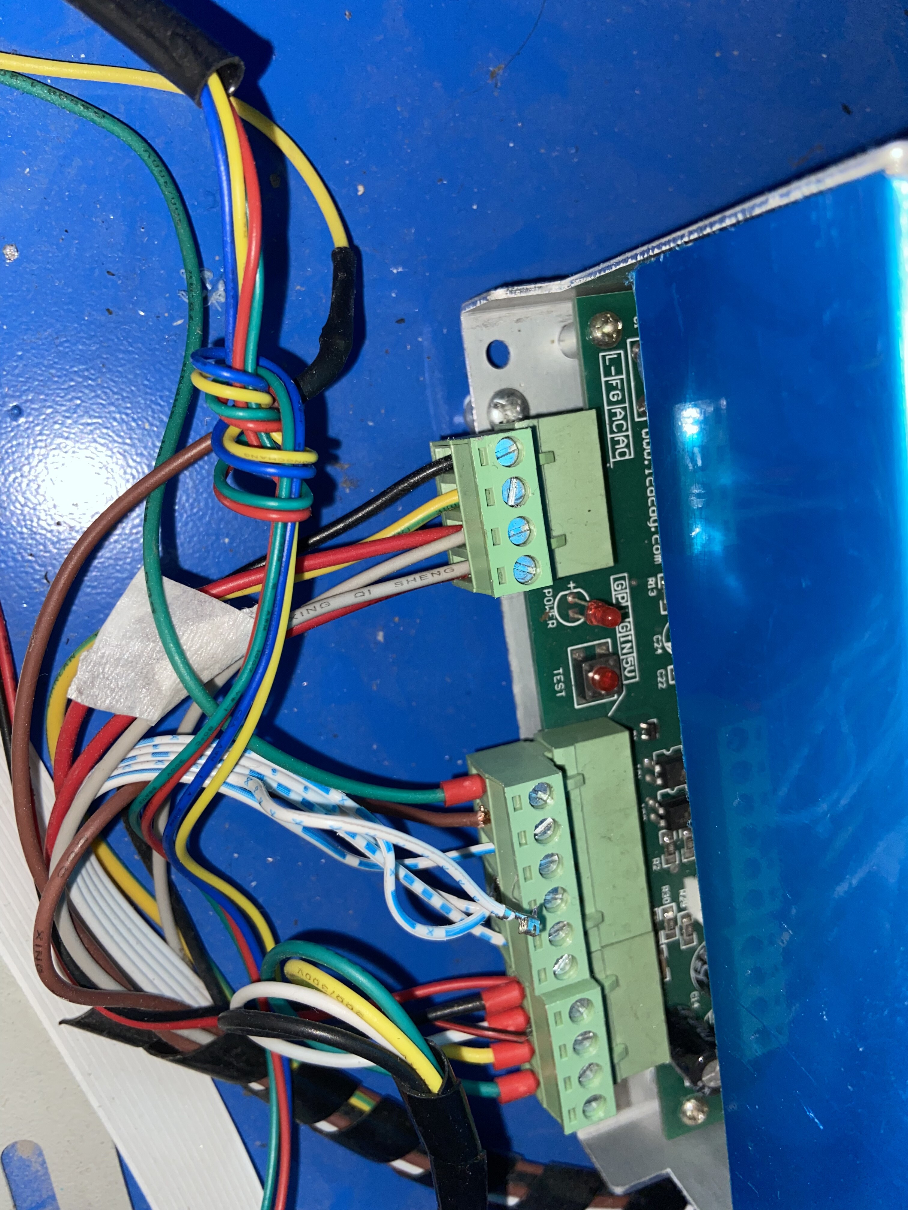
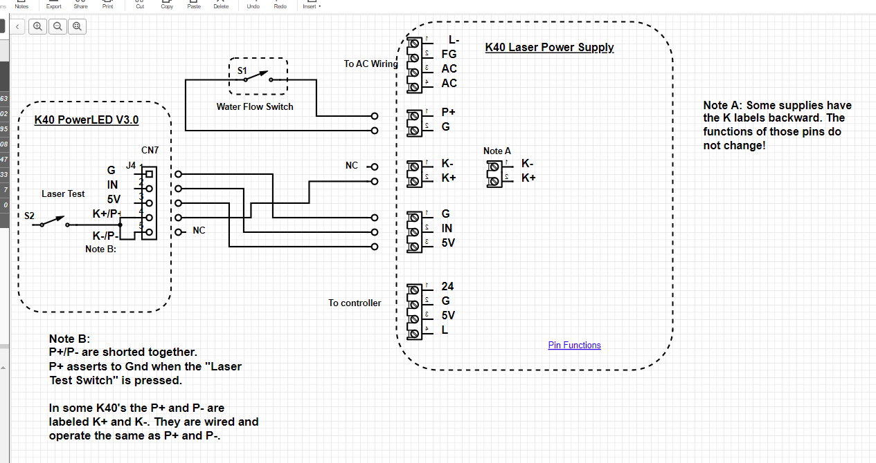
Close-up of your current LPS showing the connectors
Close-up of your new LPS showing the connectors
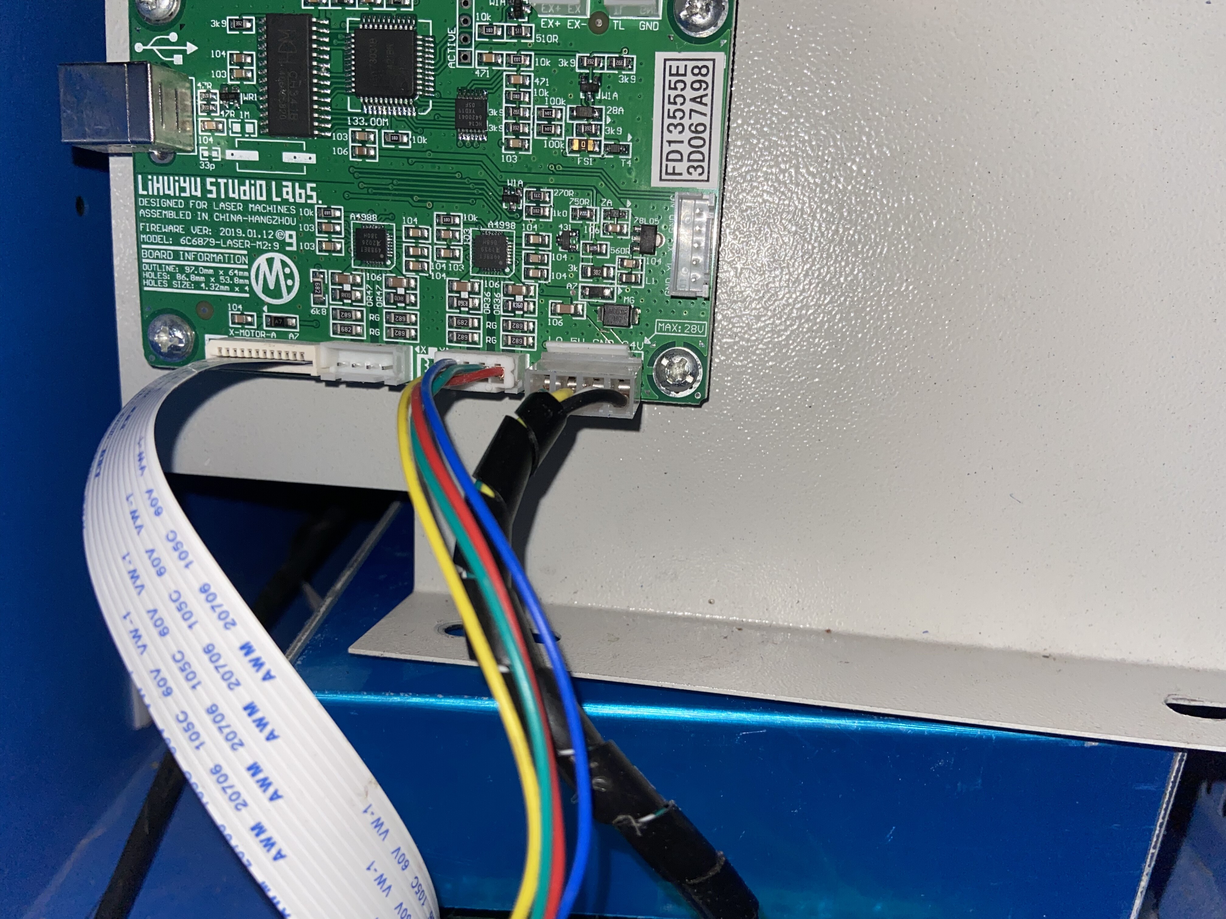
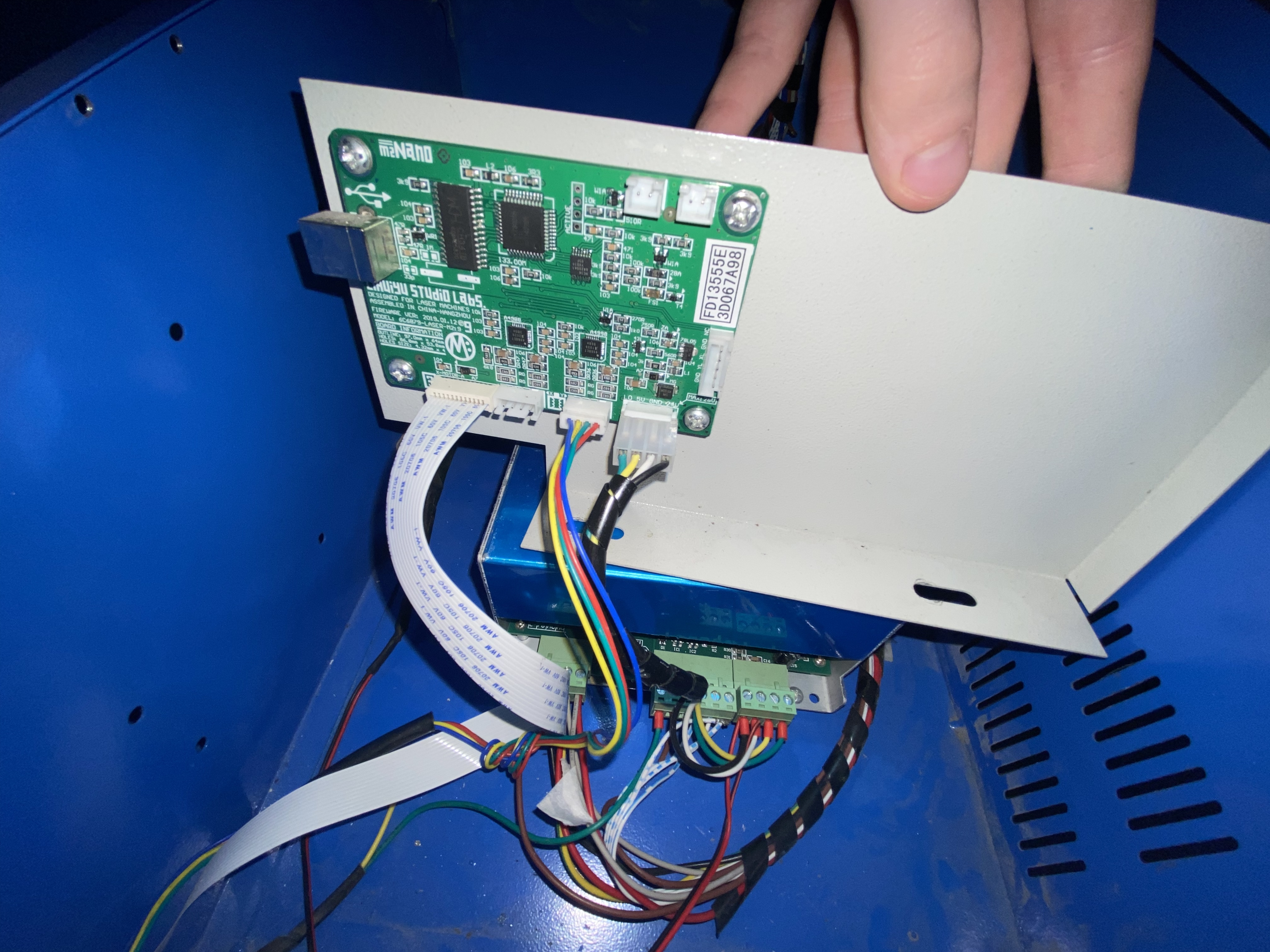
Close-up of the controller (nano) showing connectors.


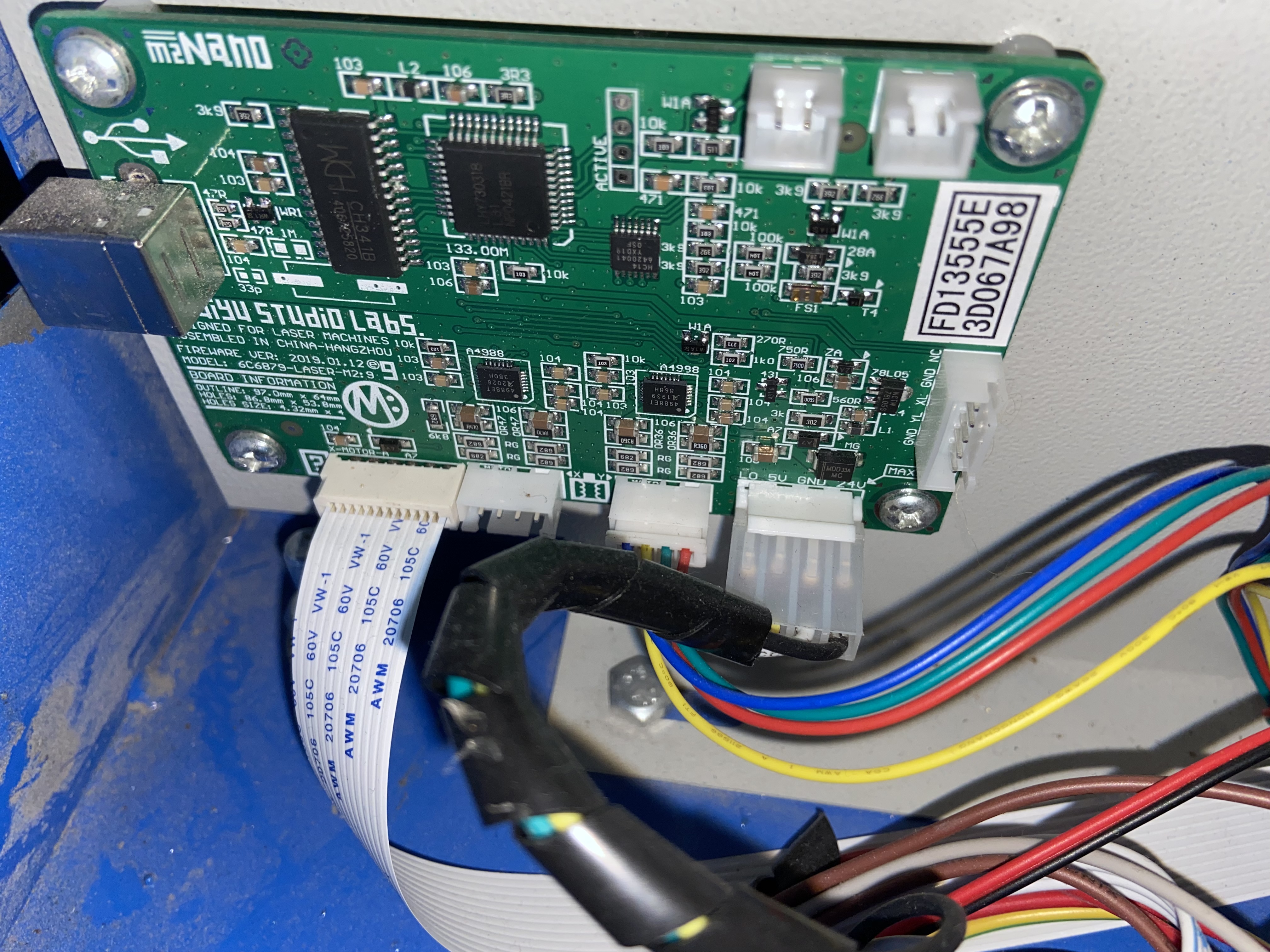
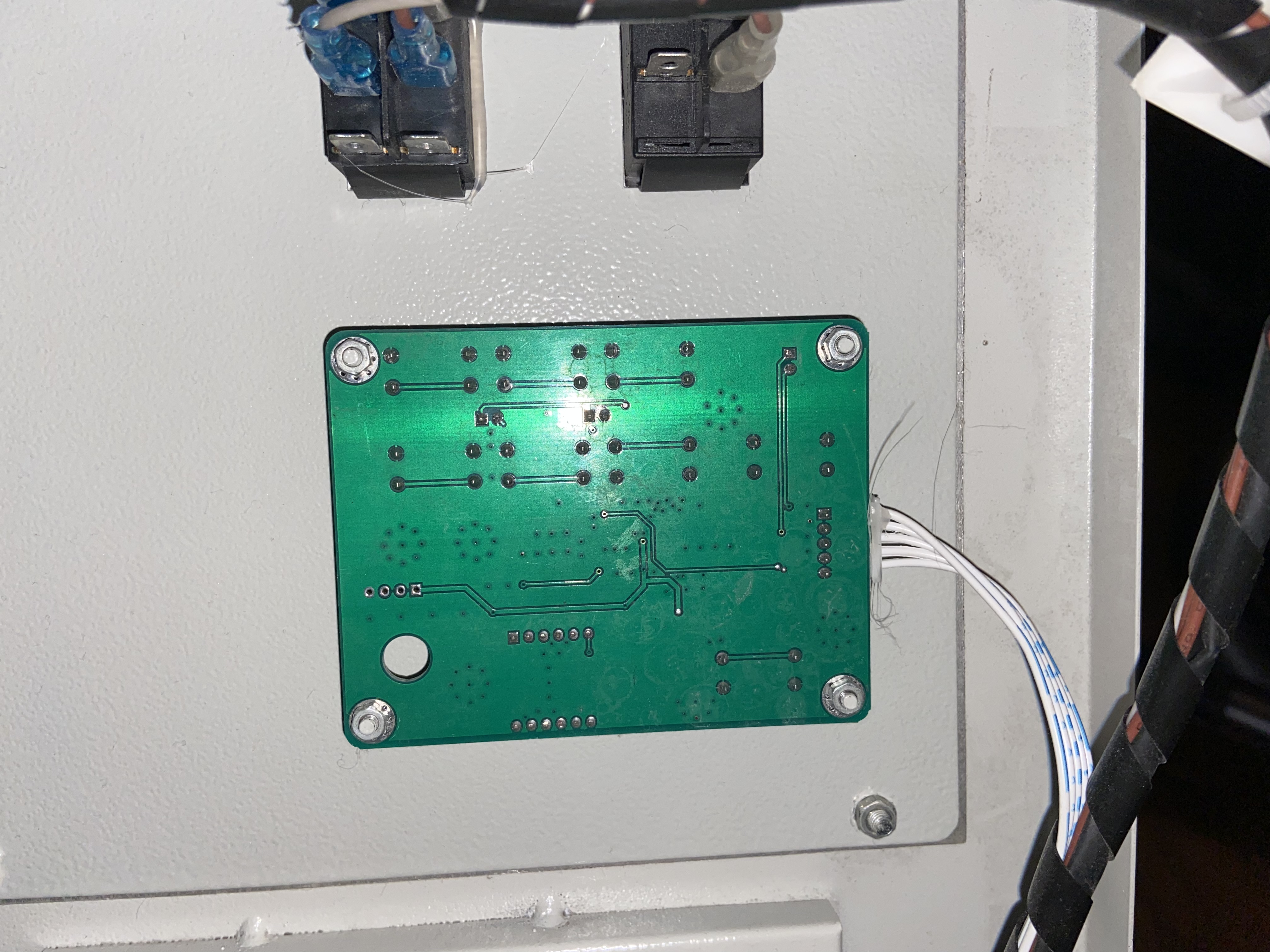

Thanks I need a better view of the wire colors plugged into the Nano’s right 4 pin connector.
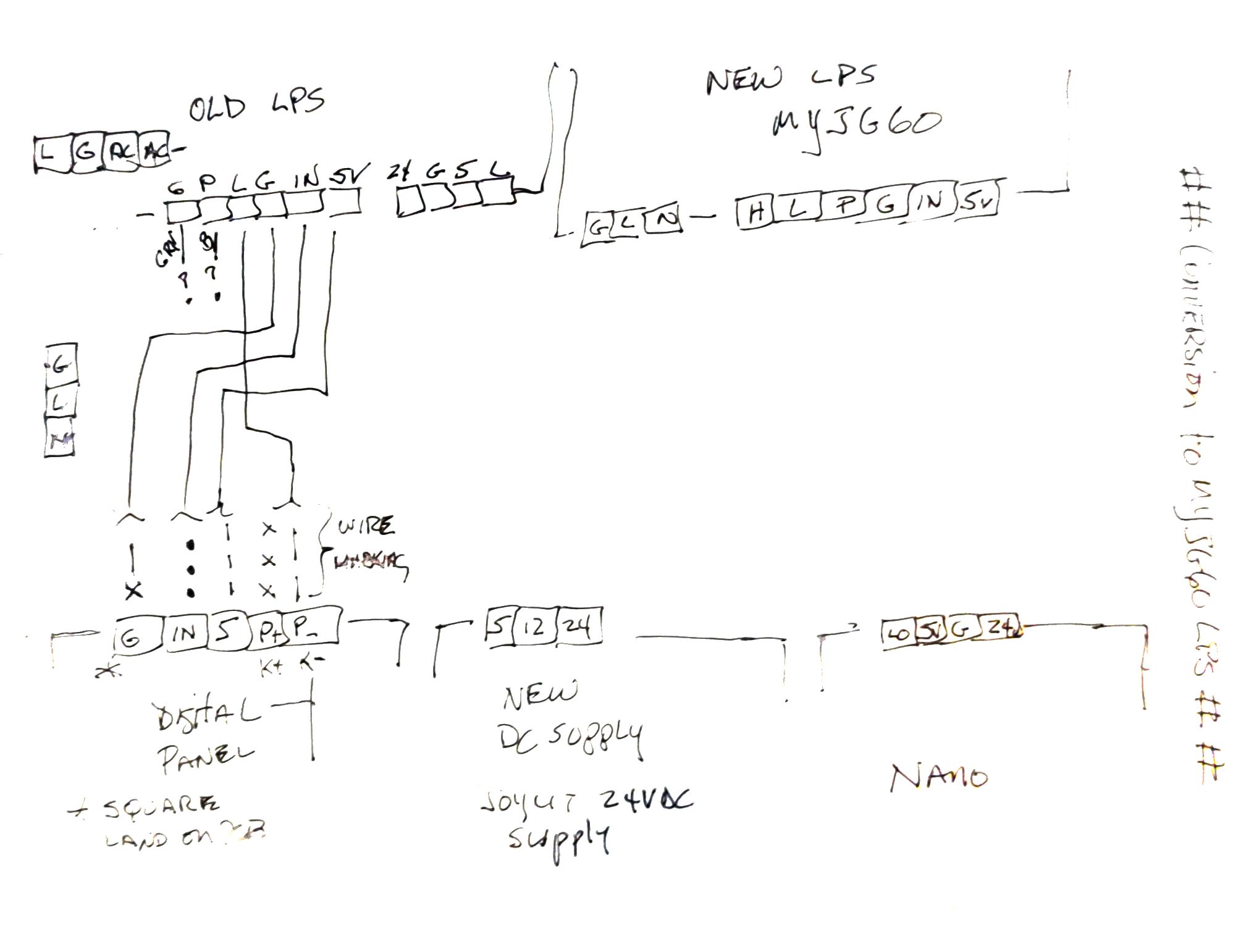
Can you trace and provide a drawing of the existing wiring from the Digital panel to the LPS? These are white wires with dashed highlights.
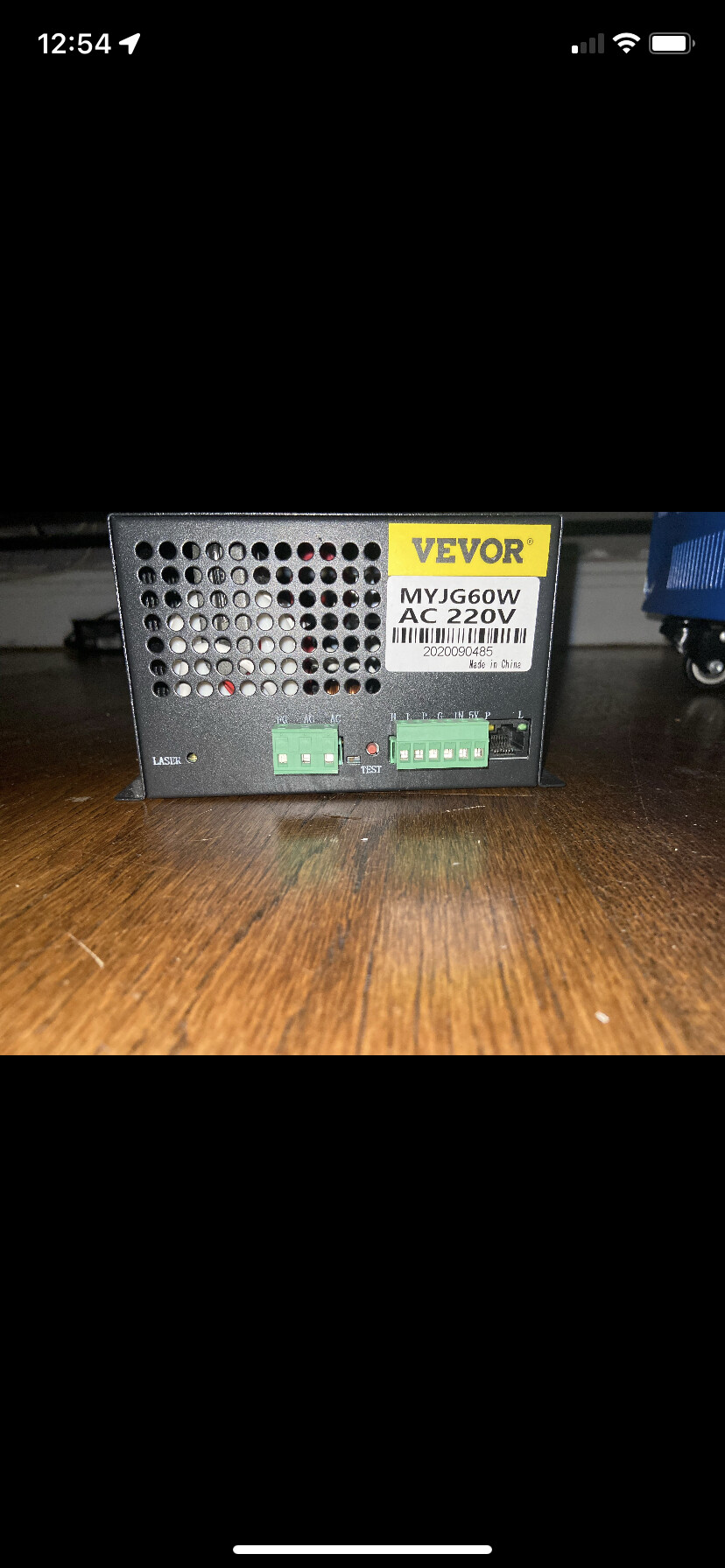
Is there a model # on the existing LPS?
What DC supply did you buy?
Do you have and can you use a DVM?
Hi, I’m at work atm I’ll send you that info in about an hour, thank you very much for your help btw.
NP… reply when you can ![]()
BTW: while you are at it you may want to consider adding a current meter.
The digital panel does not show you the tube’s current and that is an important parameter to watch.
Are you extending the cabinet to fit a 60W tube?
1 Like
Hi, yes I’m going to include a current meter and am going to use a pvc housing for the laser tube. I was drawing a diagram and noticed K+ is disconnected (must have occurred when I was unscrewing the nano) and am unsure where it goes back in.
Please at least line it with conductive tape that is well grounded. Keeping the laser inside a metal case is a safety feature; if the tube breaks and the electricity “wants” to start arcing somewhere you would like it to be to something conductive connected to ground. And even if the PVC has sufficient dielectric strength, I think it’s less likely to damage the LPS if it can arc to a ground return.
Solid PVC is 10kV/mm but some thick wall pipe isn’t actually solid.
1 Like
Don’t think that supply will meet all you need. Your nano needs 5V. That is why I suggested the multiple output DC supply.
Alternately you can add just another 5V supply.
From your previous picture looks like wire (X) it was not connected.

K+ and K- are actually connected together internal to the panel so they do the same thing. Therefore having K+ the (x) wire NC is ok. However I would put heat shrink over it.
I need you to check to verify if my wiring diagram for the cable that goes from the LED panel to the current LPS is correct.
It is the cable with the blue markings.
Please check that my drawing matches what is wired in your machine.
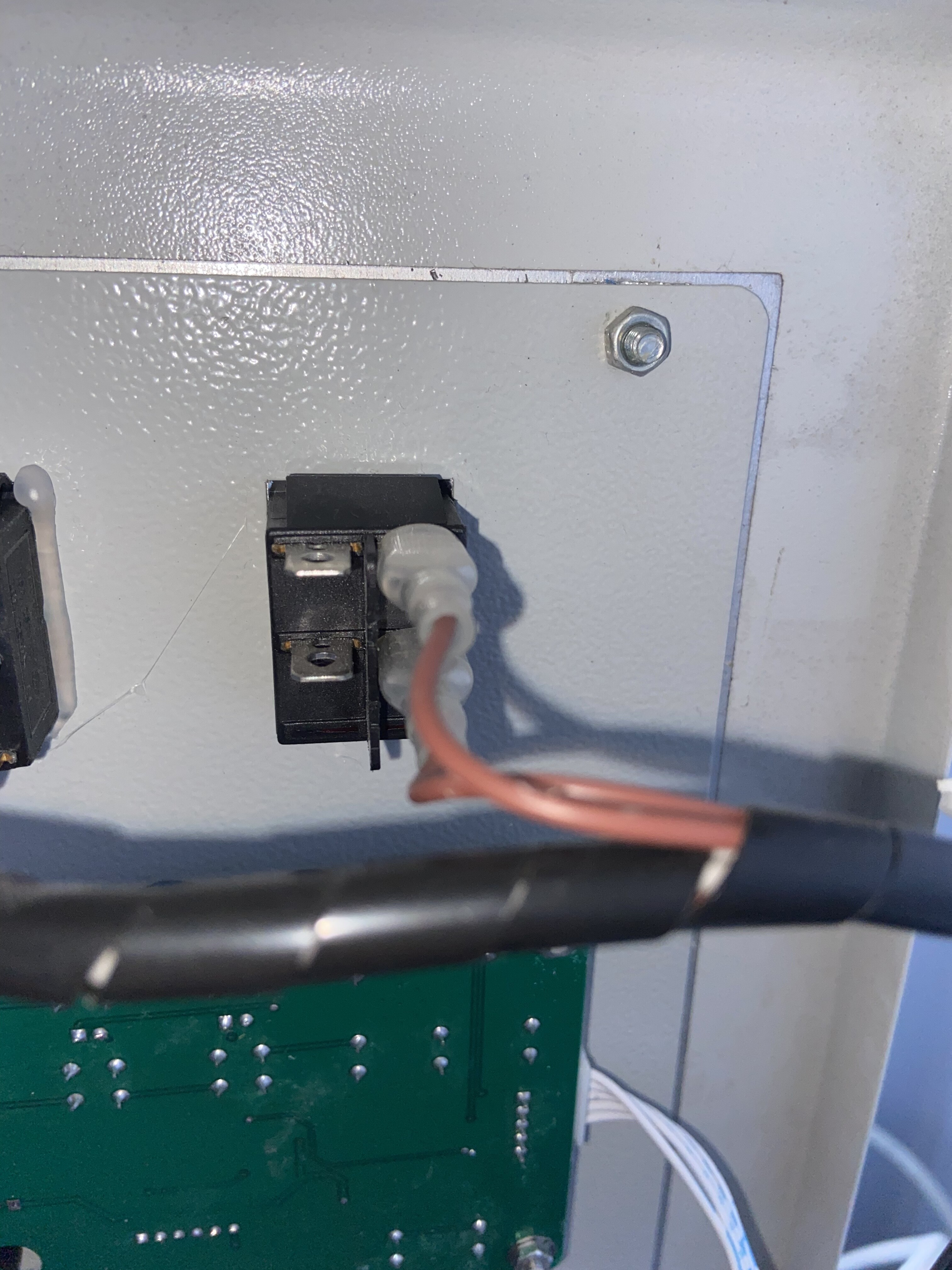
Also where do these wires go:
- Green wire on the LPS-G pin?
- Brown wire on LPS-P pin?
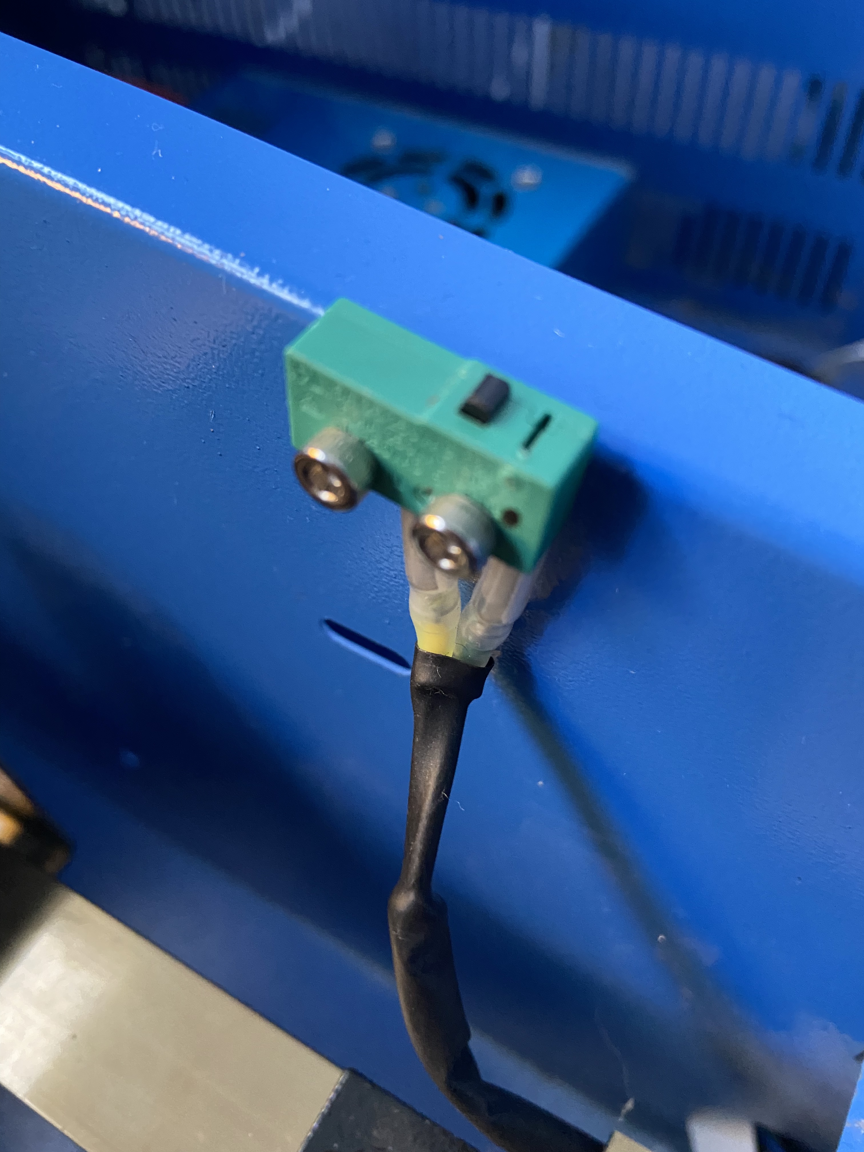
The green wire goes to the safety switch and the brown to the power switch, also is the power supply ok? When I click the link it doesn’t go to a product page.
And yes just double checked the wiring in the diagram for the psu to control panel is right ![]()