TMC2209 Driver Upgrades to a Geeetech A10

Upgrading my new Geeetech A10 printer to use TMC2209 drivers in place of the A4988 drivers to make the printer quieter. I could have used TMC2208s but @mcdanlj convinced it was worth the couple extra $ per driver to get the TMC2209s because:

I got these BTT ones.

https://www.amazon.com/gp/product/B07ZPYKL46/

Because the trinamic chips like the 2208s and 2209s have the motor direction reversed, compared to the A4988s, you have to either swap the motor wires on the board connecters or change the motor direction in the firmware.

I’m flashing a custom marlin firmware build by Vert that has support for Geeetech’s printers baked into the firmware. So I’ll be able to handle the change in the firmware.

(Edit: Vert’s fork of Marlin is no more. Vert has joined back with the Marlin community and all his work has gone into the main Marlin build. Video linked below on how to upgrade to Marlin for the Geeetech printers)

The Geeetech GT2560 control board doesn’t have native support to allow software control of the drivers so I will need to check the Vref of the chips and make changes if necessary. After consultation with mcdanlj I found I could set the Vref as high as 1.4V with the 1.0A stepper motors on the printer, but we decided to set it a bit lower to be safe.

(Edit: Apparently you can have UART support of the TMC2209 drivers with some extra work. See the linked tutorial below by @Holzleim)

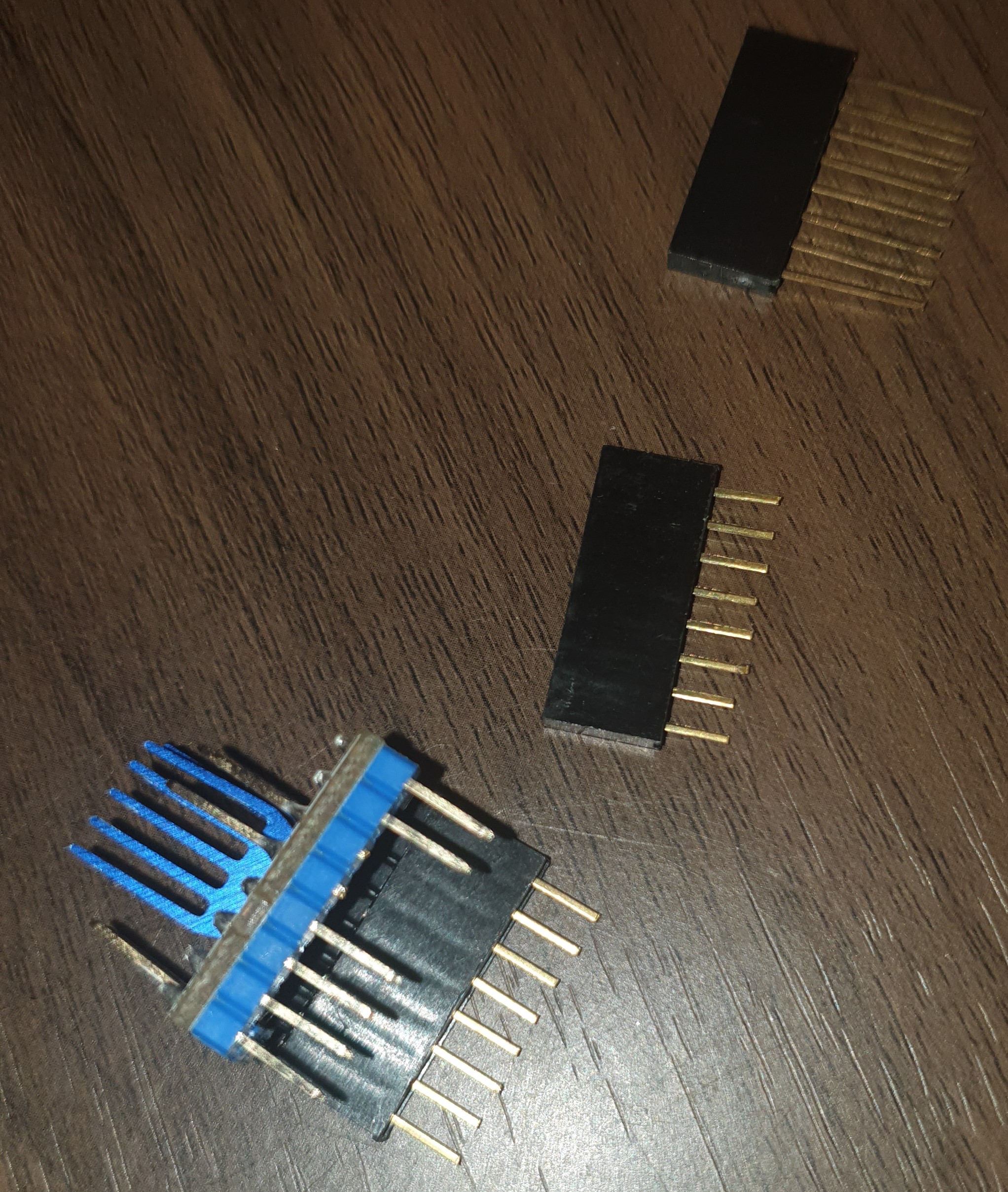
When installing the 2209s be sure the Gnd and Dir pins are on the same end as the A4988s (The Vref pot is on the other end compared to the A4988)

I measured the Vref on the stock drivers and found they were all set to 1.0V. After installing 2209s I checked default Vrefs and they were all 1.2-1.3V. I decided to lower them slightly to 1.1V. ( Note: Vrefs are measured between the Vref pot. on the driver and the case of the SD card reader.)

For the firmware I found this guy on Youtube that goes by HL Modtech. He does some great videos and has a super chill speaking style that I dig. Here is a video he’s done on upgrading his Geeetech printers to the Marlin firm ware build.

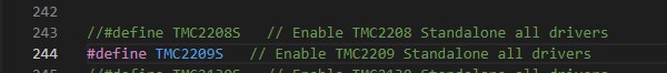
He walks you through in detail on how to get, edit, compile and install the firmware. Super easy. I did all the same edit’s he did but I also uncommented the TMC2209 in the firmware.

TMC2209 uncommented

Note that if you have been using Repetier Server to connect your printer to your computer you need to make sure it has disconnected from the printer. Otherwise you won’t be able to install the firmware like he shows. It threw me briefly because I didn’t realize it was running in the background.

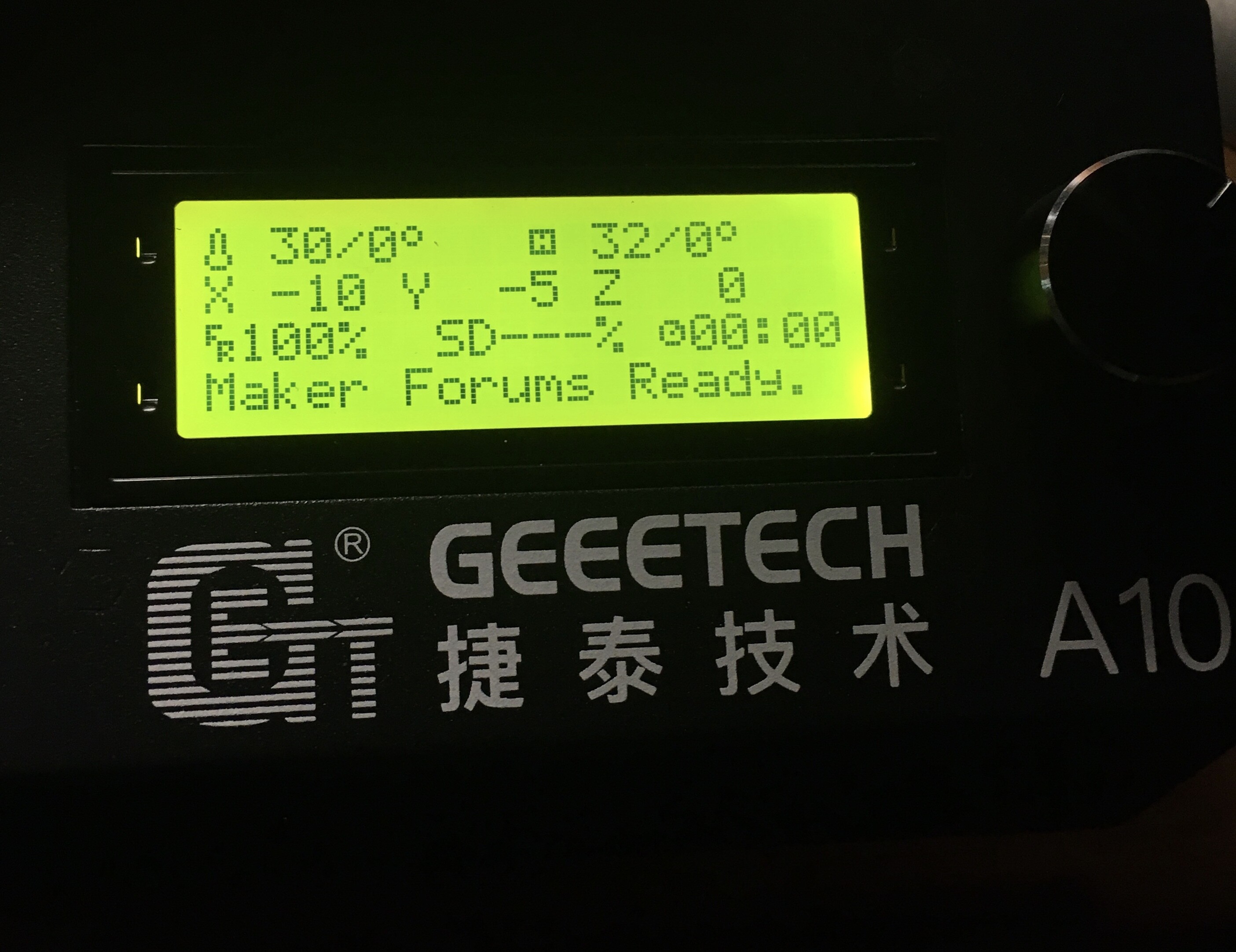
After uploading the firmware I hit the printer reset button and viola!

Did a test print and man that is sooo much quieter while printing. :smiley:

2 Likes

He is really good in the makerspace. He has some great videos on Tinkercad as well as laser projects using a Glowforge. I have encouraged him to come hang out here on the makerforums a few times. He is going to be purchasing a laser soon and said he would. The Glowforge is used for teaching high school students.

2 Likes

Hi there,
I am very new to this forum and you made me do this reply because of your sentence:

The Geeetech GT2560 control board doesn’t have support to allow software control of the drivers

This is not quite right. You can add software support with a bit of soldering and marlin configuration.
Because I can not find any tutorial so I made one by myself and pushed it on Github.

Best regards from Germany,
Holzleim

3 Likes

Hi and welcome to the forum! I thought there might be a way to use UART on the A10 with some extra work, but had not found any details about it. Thanks so much for sharing the tutorial. :slight_smile:

2 Likes

Welcome and thanks for sharing!

1 Like

Ok, so it looks like the UART header on the Ver 4.0 board is on the far right with a header plug port attached. No driver jumpers though, so not sure how to address each one separately then.

Geeetech still hasn’t put out the schematic for the 4.0 board as far as I can tell.

1 Like

I also can not find a wiring diagram for this board, but I found the bottom side and there is a TX and RX label for the header (so they are mirrored if you look from above).

It seems like the jumpers are replaced with fixed smd resistors above the capacitors (under the MOTOR headers). They have to be pull-up resistors, because the standard A4988 and TMC2208 have already integrated pull-down resistors. I see several options to set the address for the TMC2209, but all are not very elegant:

  1. unsolder all unnecessary resistors - this is probably very hard, because they are very small between plastic sockets and solder them back in is even harder, so it is probably not easily reversible.

  2. cut the pins on the drivers to disconnect them from the pull-up resistors on the board and the internal pull-down connects them to GND. Cut a different combination of MS1 and MS2 on all drivers so you set the address this way - easy, but not reversible.

  3. paint the pins with some insulating paint/varnish, but I never tried this so I am not sure if this works in a socket - this should be reversible, because it probably can be sanded down.

  4. put another row of connectors between the board and the driver and cut these instead of the drivers directly. I am not sure if this will be too high for the case, but it is reversible. something like this: https://www.amazon.com/-/de/dp/B07J5B9LT5/

3 Likes

In Marlin you can find the pins for V4 and V3. There are only very little changes at least for Marlin.
A10 V3 Marlin 1.1.8: https://github.com/Geeetech3D/Prusa_I3_3Dprinter/blob/master/A10_marlin1.1.8/Marlin/pins_GT2560_V3.0.h
and
A10 Pro V4.1 : https://github.com/Geeetech3D/Prusa_I3_3Dprinter/blob/master/A10Pro_HW4.1B_FW2.3/Marlin/pins_GT2560_V3.0.h

But the UART is not in it and it seems like it is not used by Marlin by default. No information about the jumper/resistors so far.
The DEFAULT_AXIS_STEPS_PER_UNIT in the configuration.h stayed the same for both versions as well, so it is very likely the resistors are pull-up resistors on the board, because both have the same stepper configuration i.e. jumper configuration.

3 Likes

Also remember you have to add an extra resistor between RX and TX for each driver in the wiring. That is because you bought BIGTREETECH v1.2 (your amazon link) and use the correct PDN-UART pin.
Chapter 8:
https://github.com/bigtreetech/BIGTREETECH-TMC2209-V1.2/blob/master/manual/TMC2209-V1.2-manual.pdf

3 Likes

Thanks so much for the information! :smiley:

1 Like

I have a lot of these connectors I mentioned above and I don’t need them because they are often shipped with esp8266 boards or arduinos, so I just tested my option 4 with my v3 board:

first I cut the pins to the correct length

and then put it back in

the cover fits very tight. the heatsink is not the problem, but the cables are - so maybe the RX and TX (PDN-UART) pins have to be bend to the side

with this method you don’t have to cut the drivers at all and only the connectors

5 Likes

I own Geeetech GT2560 control board V4.0 (A10T has no jumper under driver) and I bought 5 TMC2209 V3.1 drivers.
If I understood correctly from Jonas can I set addresses for UART mode by cutting pins and / or MS1 and MS2 which means I can only create 4 addresses? What do I do with the other 2 drivers? Any advice, please? Thanks.

I think the answer is that the TMC2209 can only address 4 devices on a single UART (see the datasheet). However, my Geeetech GT2560 V3.0 seems to have 2 spare UARTs - in the schematics one is labelled UART, one labelled UART_LCD, so in theory with 2 UARTs it can address 8 TMC2209 drivers. The UART_LCD connector is just pads for a surface mount FFC connector, but it should be possible to solder to those pads and get the use of both UARTs. I have an A10M so have 5 TMC2209s, and need to work out a way of addressing them all too. At the moment I’m just in standalone mode.

1 Like

Thank for antwort,but how work for you standalone because I already instaled and work really bad.Noise and just 1 way.

Sorry reply