Thought I would post an update on my “snails pace” K40-S build. As you recall I posted the Sketchup model for this approach which keeps the power supplies internal and adds an external controller module with everything else.
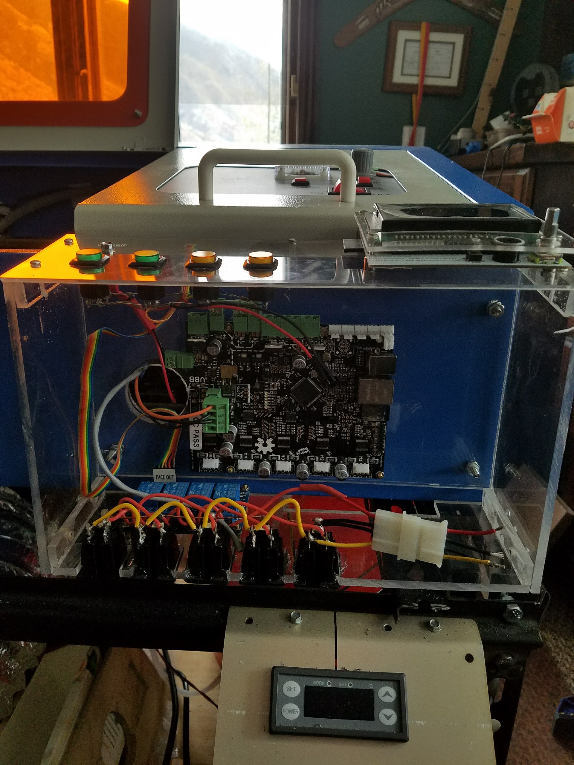
The controller, DC power, control panel, interlock interface and AC control panel are all modular and can be assembled, tested and dissembled separately. The controller and associated packaging design can be used for other projects … my CNC?
Most everything is installed and all wiring but the interlocks is complete. I am hoping for “power up” tomorrow.
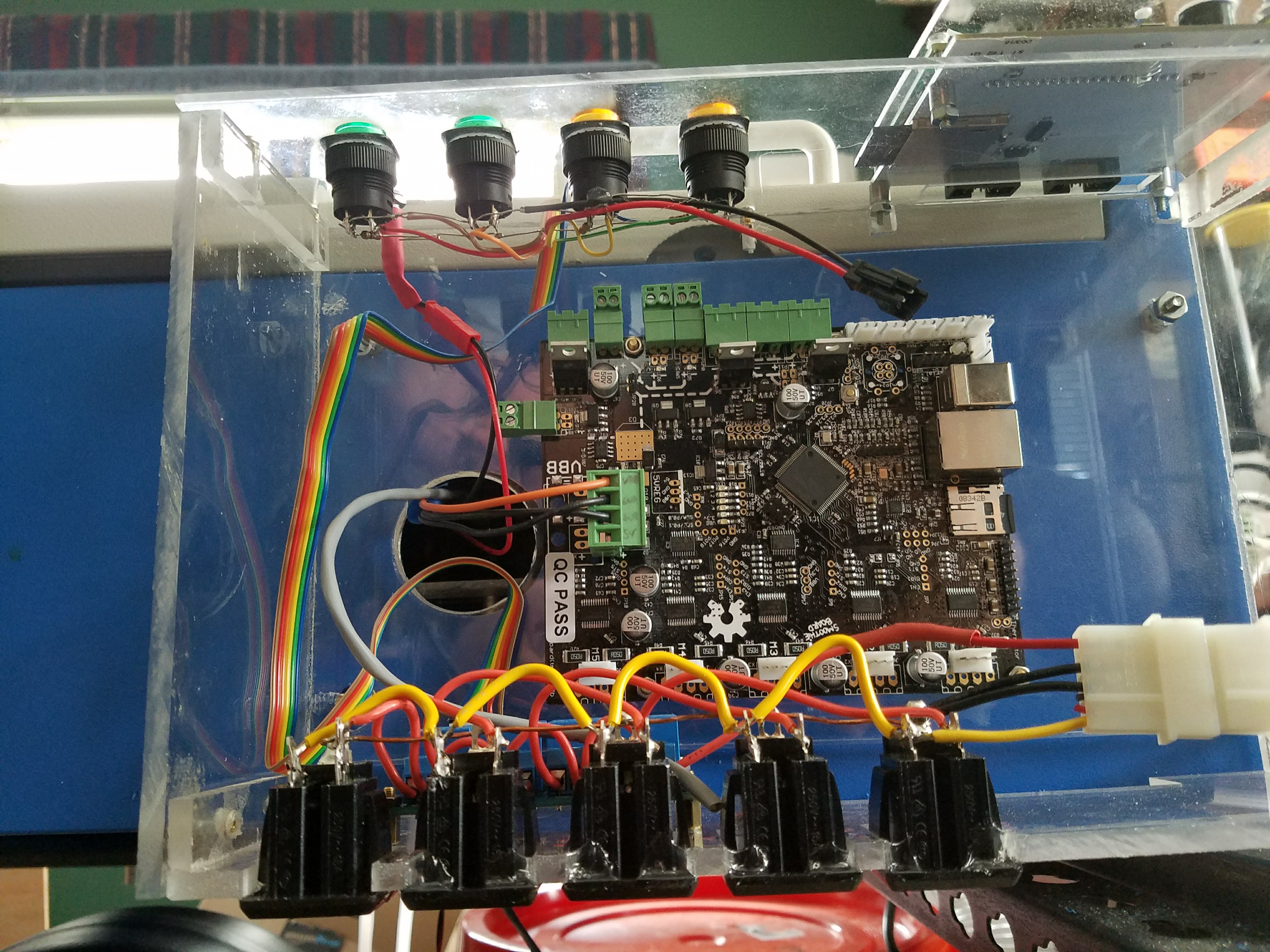
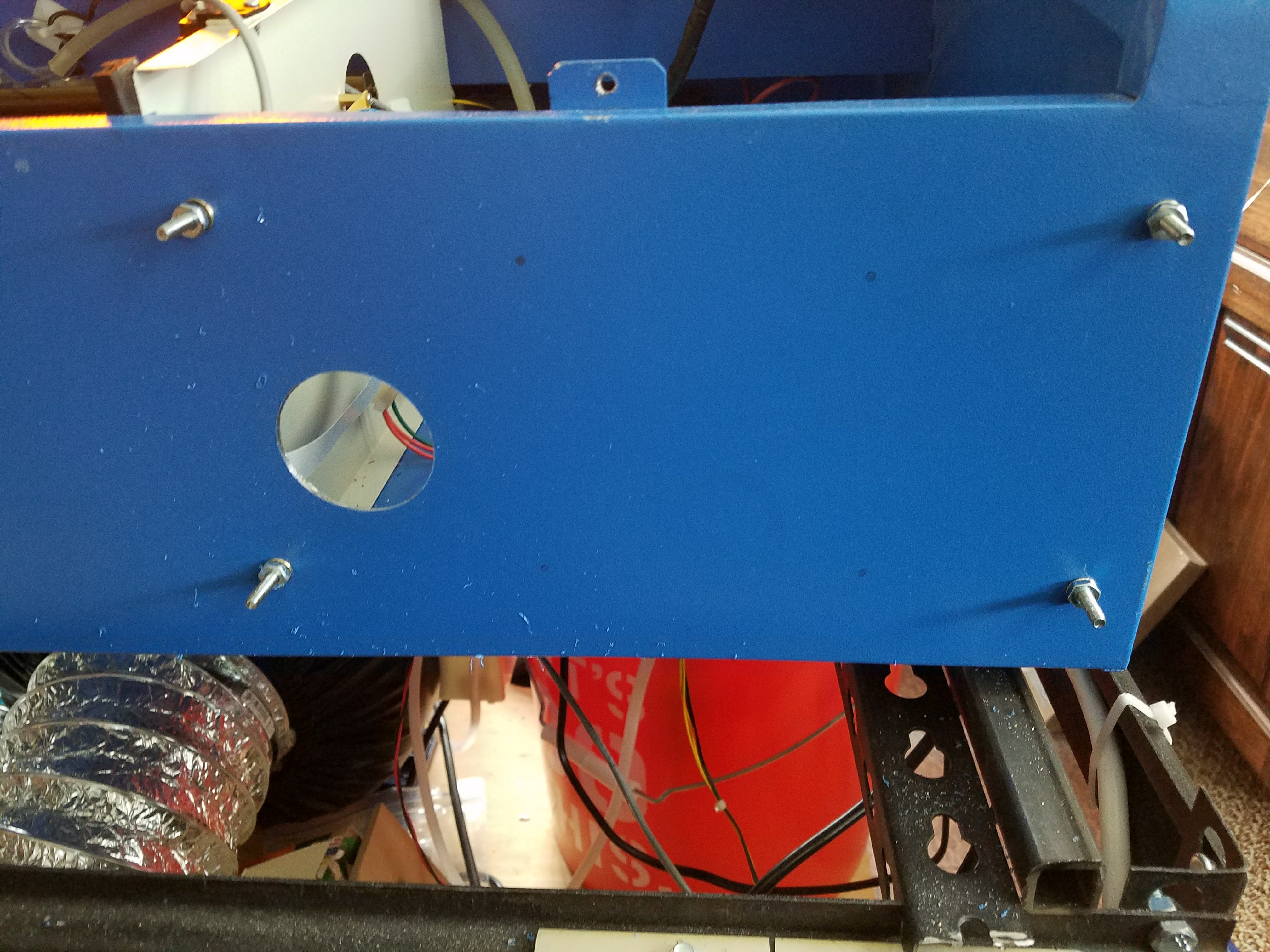
I plan to paint the inside surface of the enclosure blue but for this version elected to keep it clear so I can see everything. The front cover (not shown), swings down for access to the SD card and cables. All the enclosures/modules parts can be laser cut.
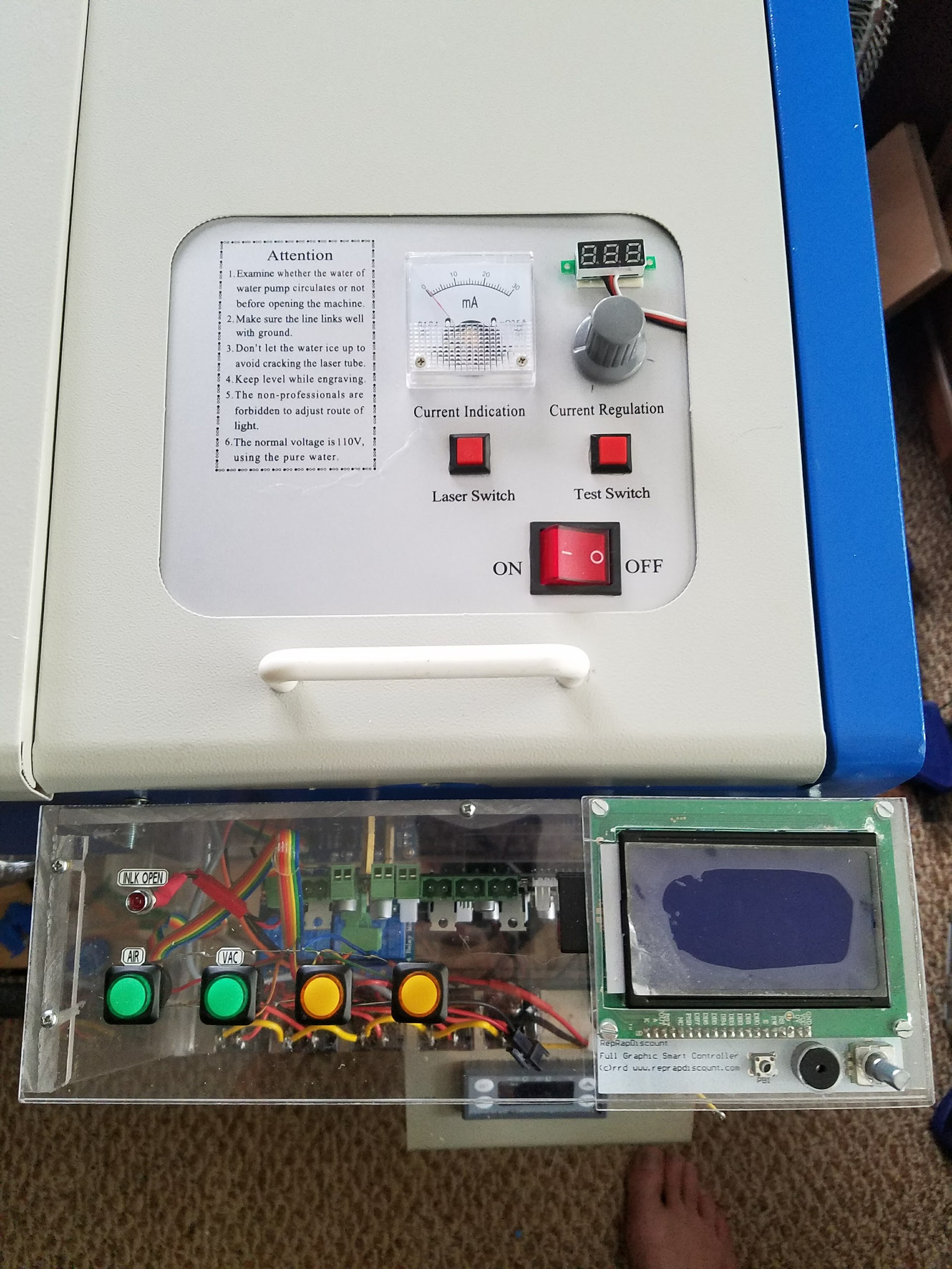
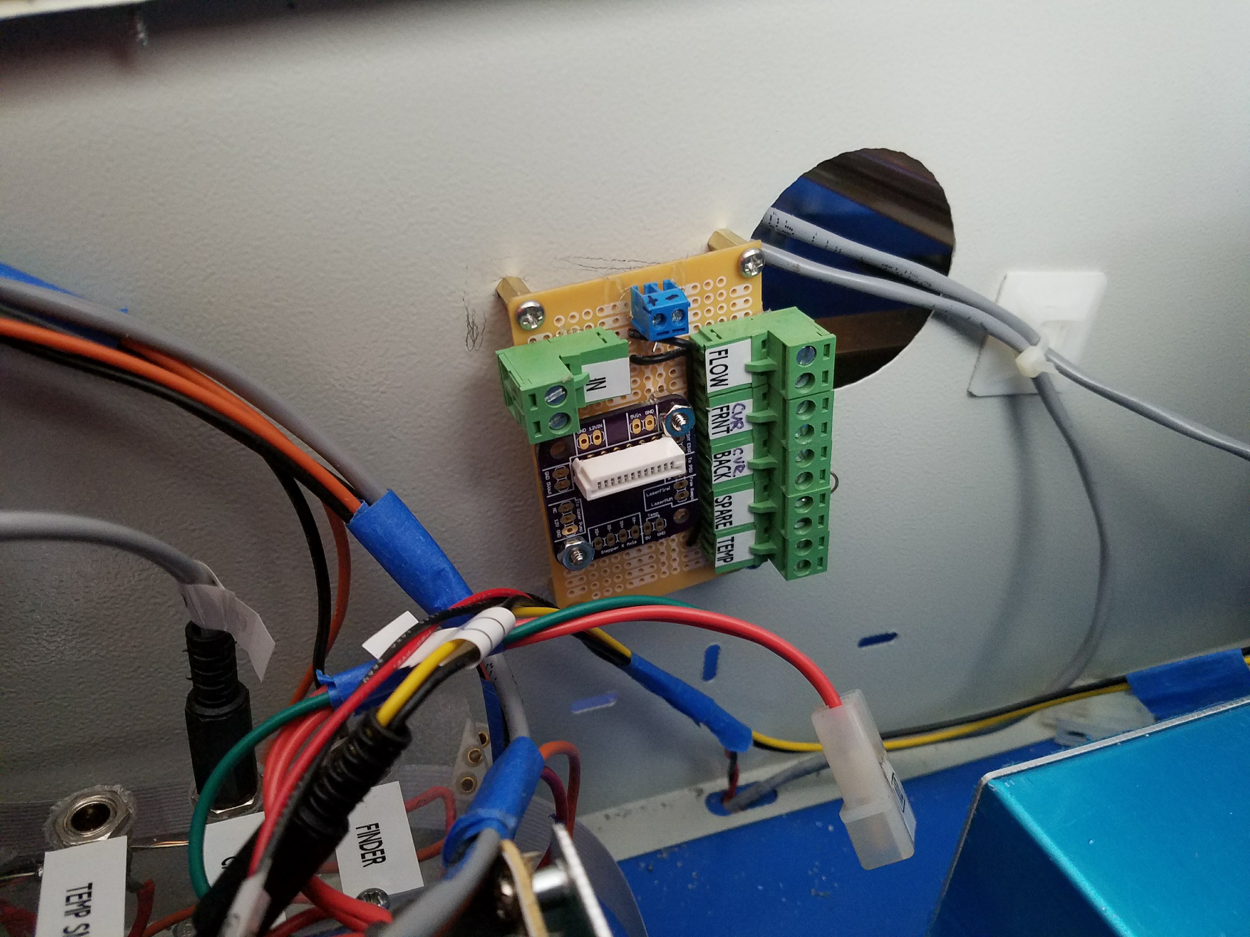
Note: The temp meter below the controller will be moved to the main panel next to the current meter and that panel will be repainted.
This modular design supports interlocks with easy wiring and interlock open indicator, temp measurement, smoothie with cable strain reliefs and access to SD card, LCD panel with SD access, modular lift table, water pump, cabinet lights, 4 relay controlled AC outlets that can be control panel & processor controlled (air, vacuum and two spares) , one outlet that comes on with main power (water pump), two spare AC outlets. 6 fused DC circuits with plenty of 24V and 12VDC power. A few spare connections and buttons for stuff I forgot.
The lift is also modular with its controls on the lift. The K40 24VDC supply powers the lifts stepper drivers and controller.
Why use the crap stock extractor housing when you could have straight down draft extraction,thus preveting fumes running acrss and marking the work peace
@Phillip_Conroy Do you mean the extractor that is inside the laser compartment (there is not pictures above of that)? I plan to remove it after this hack is working as the gantry will need to come out. I dont know yet if I will just remove it and leave the rear exit or extract out the bottom. I plan to eventually cut out the bottom to accommodate a lower lift table.
Down draft extraction is the best way to avoid any fume marks on rear of cut stuff,if i did nog have a wooden desk i would have this mod in a heatbeat,it also helps to hold the wprk peace in place
Yes the extractor fan in cutting bed,i had a look at your old posts of yours -nice custom exit of laser cutter fumes,if i didnt have a wooden desk i sit my laser on i would have down draft extraction in a heartbeat
Thank you! Question. What’s the J36 block? Is it just a terminal block? I want to wire mine up without actually connecting it to my board. Just a simple way to plug in my accessories and add a switch to turn them on and off. I was just going to splice in a switch into the hot wire, but if I can avoid actually cutting the power cords to my accessories I’d prefer that.
@K1111 can’t find J36?? Currently my setup is not wired to the Smoothie control.
The relay board is controlled by the switches and the relays control connecting the line to the AC sockets. AC control currently is independent of smoothie. I will post some wiring pictures.
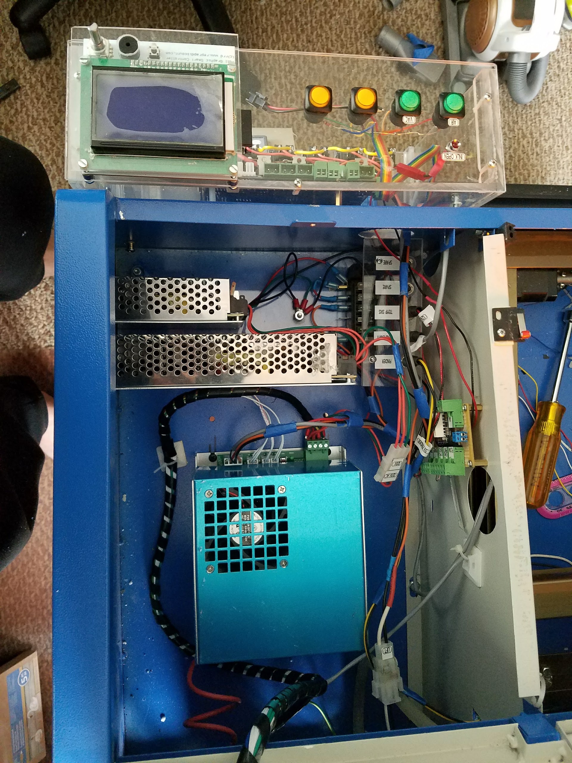
This shows the AC source. I disconnected the LPS and put a terminal block in so I could connect multiple things to the switched AC. The black and white wire goes through the cabinet and out to the AC control.
The AC control seen in this picture has the switches wired through a ribbon cable to the relay board. The relay board is wired to the AC sockets. The connector with the red and black wires is the AC source.
No it does not run through the LPS. The LPS is one of the modules that uses AC power.
The main switched AC (the control panel on-off switch) is connected to the LPS.
I disconnected that, connected it to a terminal block so that I could use that switched AC to turn on power to all the stuff in the machine.
That means that when the main switch is off so is all the stuff in the machine i.e. LPS, DC supplies, and anything connected to the AC control sockets which is air assist, vacuum and pump. Note: the pump is not controlled and comes on with main switch.