The culmination of about 3 months (total time - on and off) of testing and analyzing.
I’ve managed to greatly improve the cooling of the e3d v6 hotend, more specifically – the upper part of the heatbreak that connects to the heatsink.
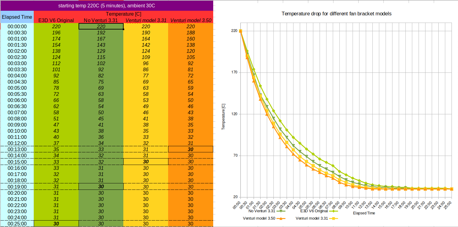
This is even compared to my previous endeavor ( https://www.thingiverse.com/thing:2769783 ), and improves/reduces any jamming that may occur due to heat-creep and also reduces retraction distance (which, for me, has greatly reduced stringing).
i’ve done this by optimizing the cone shape and angles of air flow, as well as the internal shape of the hotend holder.
This was all done “old school iterating” by printing and testing different configurations and documenting and measuring trends and differences to find the optimal configuration.
But I still think there’s room for improvement, and would like the help of anyone with cfd experience and/or software (like solidworks or autocad inventor) as my attempted analysis with simflow was a complete failure and a waste of many hours.
Just as with my previous work, the design will be fully open source and available in stl and step formats for anyone who wishes to play with it (as well as the full f3d model). It is also fully compatible with the previous generation of attachment plates, so it’s just a single print of about 8-9 grams and about 40-50minutes.
I am making the painful move from onshape to fusion360, which caused a further delay in finishing this design, so if anyone here knows how I can share the full design online (as with onshape), instead of just posting the f3d file - that would also be highly appreciated.
in case anyone is interested - full details of how the analysis/comparison was conducted are on the thingiverse page, as well as the model itself if anyone is interested in conducting their own tests (for validation or use), or helping out with optimizing air flow.
@Janne_Grunau - reading through that post, it does seem like they adapted a similar approach with a venturi effect tunnel.
just to be clear, their post if from july 14th and my first git commit on this project was on june 3rd (about a month prior), so this has nothing to do with their design.
i’m glad to see that someone else thought about it, though my inspiration came from a youtube video about a DIY sand blaster.
tbh - i’m still quite surprised this makes any difference at all, since my initial calculations indicated not enough air would flow to create the venturi effect.
i am still not a big fan of their extruder/cooling setup and i think it is a great example of how a bad hotend cooling setup can really ruin a great machine (i have some friends who constantly fight to print pla and tpu properly). hope they got it right with this r3 release, from everything i’ve read about josef prusa - he seems to be a very meticulous person.
also - you might want to check out my layer cooler outlet on the thingiverse page. their new 45 angled design is something i am not really fond of (adding the connector weight and causing a loss of balance to the moving train and might cause problems with the blower).
mine and their models for the layer cooling have taken very different approaches.
This is good stuff, thanks for posting. You might also consider an inlet duct to smooth the air intake to the fan. Axial fans with constricted outlets tend to blow air radially out the “intake” side and lose CFMs, and a more gradual inlet profile helps with that.
There are a lot of design-for-manufacture and cost compromises in the E3Dv6 design. A small radial blower would make way more sense than a 30mm fan — that would let you cut the heatsink length in half. Likewise the heat break M7 threads are very oversized for 1.75mm filament and thus significantly slow down heat-shedding through the low-conductivity steel heatbreak, but maintaining the same heatsink part for both filament diameters requires a larger size. Then the fan duct is well-understood to not be entirely optimal, but injection molding geometry constraints and the 30mm fan footprint basically force it to have the shape it does.
Come to think of it, you may want to verify your experiments AREN’T showing greater temp loss from the hot block because the fan is inadvertently blowing down to the hot block. A thermocouple stuck down inside the heat break would be a better way to test to rule that out, if you’re able.
@Ryan_Carlyle thanks for your comments.
there are a few designs on thingiverse for good inlet ducts, and i have used one in the past.
one of my goals here was to minimize the restrictions in air flow to improve the cooling. it took some time playing with the right cones/shapes to cut in the model, but i think it’s pretty optimized. it’s one of the reasons i would like someone’s help with running some cfd simulations, as the only tests i am able to perform are feeling for any back air flow with my hand and with a piece of paper, and comparing the air flow to that of a clip with one side completely removed.
i’ll give it a try in a few days with an inlet duct and compare the results and update.
regarding the e3d v6 itself and it’s fan clip, while i think the fan clip can be improved, this post and my design are in no way meant to dismiss or belittle anything e3d are doing, if it came out that way - i apologize.
i pretty much love the modularity and performance of the v6, you can mix and match different heatbreaks, nozzles, heaters, heatblocks, etc… and that comes with a cost when manufacturing in volume.
regarding verification of the cooler not cooling the heatblock, that is a very valid and true point.
since it would be extremely expensive for me to drill a heatbreak (11.50gbp + expensive shipment, unless e3d are willing to send me some sacrificial ones ), i tried to stick a k-type thermocouple down the heatbreak and clamp it in there by pushing a paper clip which presses against it. results were inconsistent at best, so i gave up on that.
what i ended up doing is creating a custom printed mold (modded one i found on thingiverse) for a sock that also covers the top part of the heatblock and compared those results to ones with a “regular” silicone sock, and compared to when i also jammed a piece of (what is referred to here as) ceramic wool/padding between the top of the heatblock and the bottom of heatsink.
it’s not as perfect and scientific as measuring the temperature of the heatbreak directly at a specific point, but with what i have (and am willing to pay for), it’s as much as i can validate.
tbh - i could have done something wrong anyway, or there is another bias i did not think about. which is why i’m hoping people will be willing to test the new version and also validate the results. or maybe help with a cfd simulation.
@Ryan_Carlyle The perverse part of v6 is the 3mm heat sink uses 6mm thread, making it a different part. It seems like they could have done M6 for both filament sizes.
Edit: I just realized there’s other issues trying to use the same part for both sizes, never mind on that part.
@Tom_Keidar Take the stock sock, and install it on the top of the heater block before you assemble the hot end. Then it covers the top, and not the bottom. Should insulate it adequately for your test purposes.
@Mr_Bonce - thanks! that’s exactly what i was looking for, will clean up and publish this week (hopefully - it’s holiday season here, and the whole month has ~9 days of school for the kids).
@Taylor_Landry1 - it’s a really good idea, but unfortunately i don’t have any left. i had 3 (+1 used) but they wore out extremely fast. so i bought some 2 part silicone from the german company @Troll_Factory (for another project) and made my own. they have yet to wear out at all, and i have used them up to 285C…
but, your idea is basically what i did, wrote that in the reply to @Ryan_Carlyle 's comment regarding that.
i customized an existing sock from thingiverse which already had the top pretty closed up, to be almost completely closed. except for a hole for the heatbreak and a cut/slit on the side from which you insert the heatblock (and then screw the nozzle and heatbreak).
i went a step further, to make sure no air flow was actually cooling the heatblock, and put/shoved a folded piece of ceramic wool/padding between that closed silicone sock and the bottom of the heatsink. that’s as best as i can do (i think).
 ), i tried to stick a k-type thermocouple down the heatbreak and clamp it in there by pushing a paper clip which presses against it. results were inconsistent at best, so i gave up on that.