For my 8X8X8 RGB LED cube, I needed 512 LEDs and I purchased 600, plenty for the build and some spares.
I started to wonder about the probability of brightness variations between the LEDs and decided to find a way to individually test those 600 RGB LEDS and ideally to pick 512 (and some spares…) closely matched for brightness levels in all 3 colors. I wanted to do this before I soldered them into that cube as I know that any repairs/replacements would be a serious pain !!
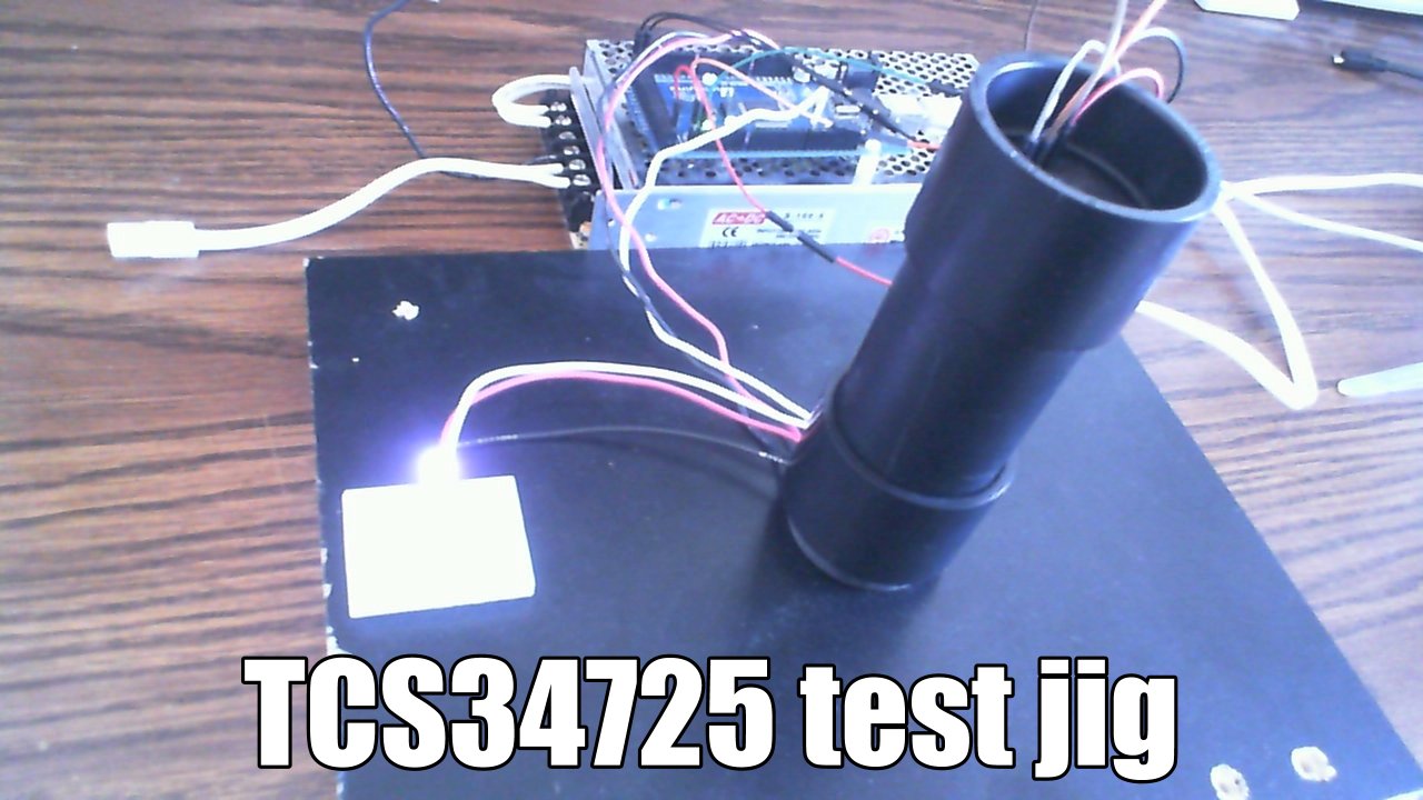
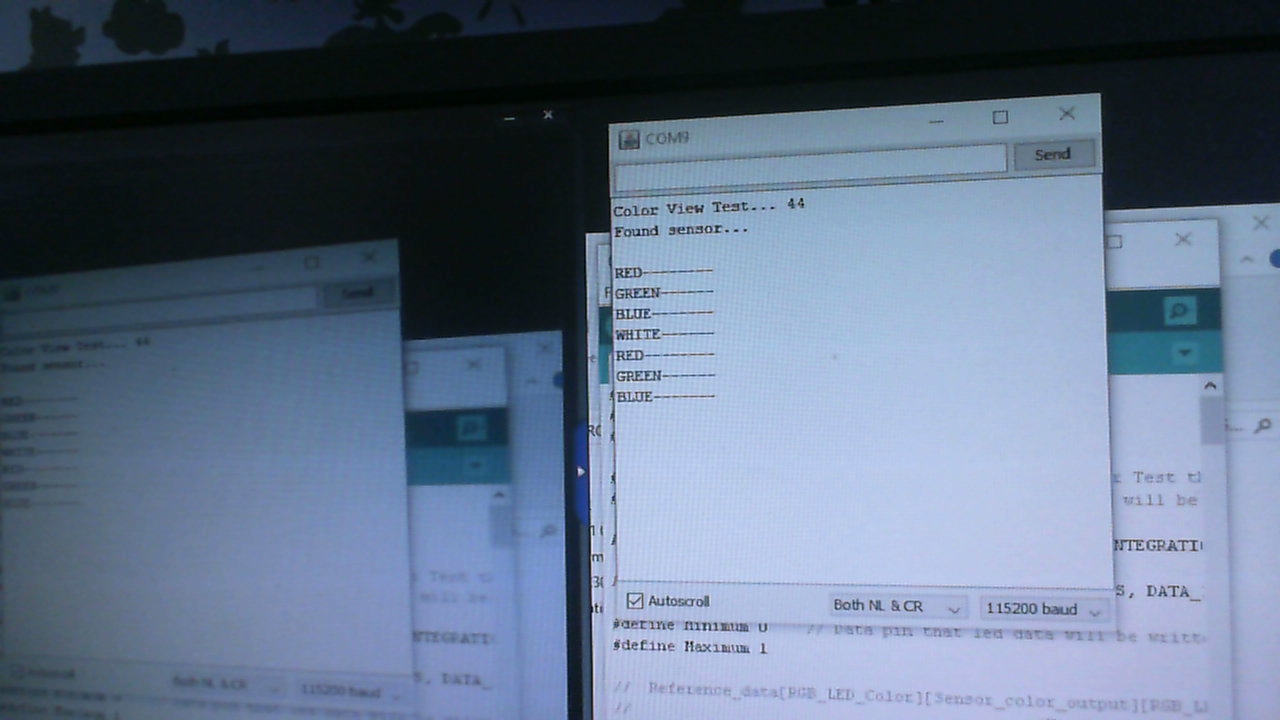
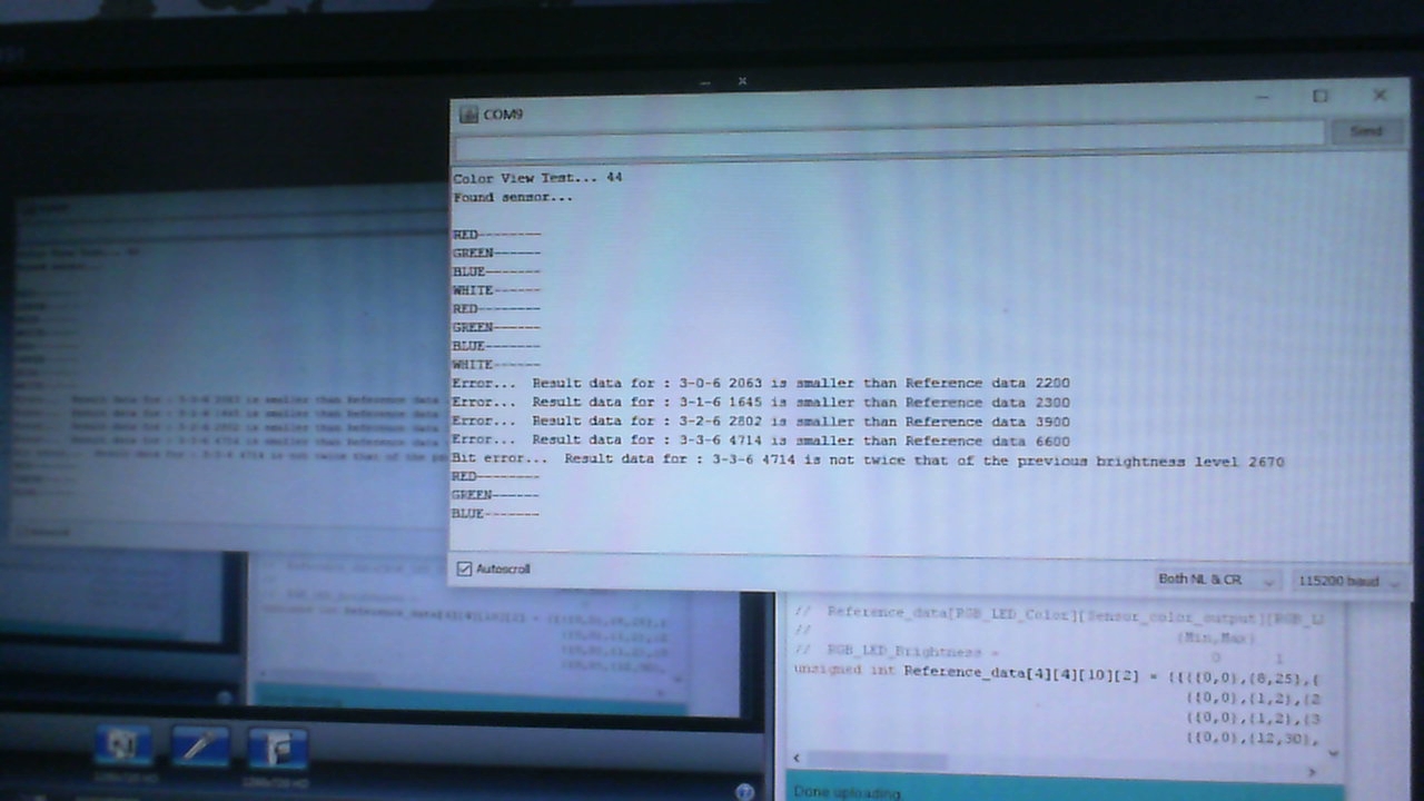
Following Jon Burroughs suggestion, I purchased a ‘RGB Color Sensor with IR filter - TCS34725’ from Adafruit and put together a jig made of some ABS pipe and couplings to create a mini dark room. I downloaded the Adafruit’s TCS34725 library and put together a test sketch that drives the LED under test through brightness values 0,1,2,4,8,16,32,64,128, 255 for colors RED, GREEN, BLUE and WHITE. This actually tests that each brightness bit is working properly in the LED’s PWM internal circuits. For each step in brightness, the sensor measures the light intensity of all 3 RGB colors and White color. I actually push the data to 2 devices to also verify the data out of the LED under test and that also gives me a visual of the test in progress.
That ends up being a huge set of collected data for a single complete pass through my test. 10 brightness steps X 4 colors X 4 measurements each = 160 measurements per LED. Actually for each of these 160 measurements, I ended up creating a table with a minimum and a maximum value for each measurement. I updated these values as I ran more LEDs through the tests as I did find variations between LEDs.
Now due to the LED’s PWM control of brightness and the sensor’s data integration times I had to make the test long enough that I did not get too much variation in the measurements because of when the sensor was measuring within the LED’s PWM cycle !
That ended up being an excellent GO-NOGO test for the LEDs and although I did find variations of the measured values between the LEDs, when I visually compared LEDs that were at the minium range for a given value and another that was at the maximum, I could not really see a difference at all so I gave up that idea.
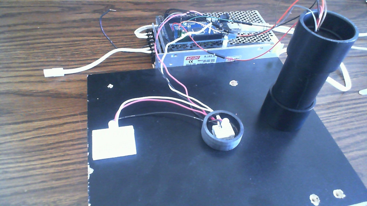
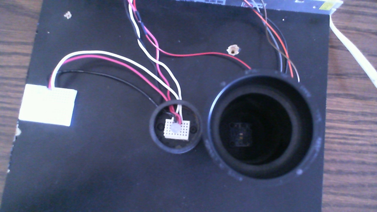
Here’s a few pictures of that test jig…
I wonder if there would be a difference between direct illumination (led shining on sensor) and perceived illumination by checking a diffused or indirect light. I guess for a direct application like a cube it wouldn’t make a difference but for other installations it could yield information.
Hi @Jarrod_Wagner ,
I don’t think so. I found the sensor to be surprisingly sensitive and most likely very accurate given my test setup.
Again, the issue of the LED under test’s brightness being controlled by a 400Hz PWM cycle may certainly be a source of error as my light sampling is also time based and the 2 are totally asynch !
With regards to my attempt to pick closely 512 matched LEDs in a bag of 600 is that the sensor’s. I started by sampling 16 LEDs that I had, to the best of my visual acuity, checked as being ‘matched’ and created a slightly widened MIN-MAX table for all 160 measurements.
For all subsequent LED tests, when any failed to fall within my MIN-MAX table, I visually compared it to my original 16 and labeled it. As I said, I did not find any real visual differences and I then proceeded to update my MIN-MAX table and resumed testing.
I updated the MIN-MAX table a surprising amount of times at first of course but then that kind of stabilised.
When I was driving the LED blue, a significant amount of green light could be measured. The reverse was true also !
The RED light stands by itself a lot more but still… I always measured some blue and green light output even when I was driving the LED RED at a low level !
@JP_Roy I actually found the same exact thing with an android app I’m developing. Even when a pixel was given as an RGB value like (255,0,0), the direct pixel reference would often contain elements that didn’t correlate to the given color.
I’m going to assume there is some complex principle in various color spaces that would explain that but I ain’t smart enough to understand that
I haven’t looked at the datasheet nor has them on a scope, but what is the time between PWM being applied to each color of the RGB led from the WS series chips?
Ie, how close is the 400/800hz PWM for each specific color when more than one die is lit?
Hi @Jarrod_Wagner ,
The 400hz is generated internally by the WS2811/WS2812 IC itself and that frequency is used for all 3 colors. That frequency has nothing to do with the data rate that is 800 Kbps.
Even without any data applied, the PWM still has to be free running within the device for it to continue it’s brightness control…
I am only guessing some kind of simple oscillator made with an RC circuit and logic inverters. I never checked on a scope or otherwise but I would assume a 5% (standard device tolerances) variation in frequency could be expected.