i have a 3040EZ Chinese desktop router-a very common gantry style “desktop” router. i’m trying to align its square to the square of an lcd display (this is to drill pcb’s that have been imagined and etched via sla method). if i’m understanding correctly this is normally done using two limit switches on ganged axis machines (2 ballscrews and motors on each side of the table-both with it’s own limit switch) where adjusting the placement of the limit switch on one side and making sure the motors stay energized to maintain position is how one aligns/squares the machine.
however i only have a single ballscrew for the Y-axis that runs down the center under the bed. can i still use the same method to align my machine? i imagine this will cause some wear to the machine, but when i think about it the same would be the case for ganged axis as well?
am i right in thinking it should still work? manual adjustment of this particular machine to change its alignment does not seem very possible or recommended given it’s construction - i feel i’m likely to cause more problems in the long run. is there a better way to achieve my goal?
Why not just use the machine to route an outside template that you leave clamped to the bed and drop the PCBs in? It will naturally orient the cut to the machine’s square and function as a fiducial for your PCBs.
the issue isn’t squaring the work piece to the bed, the issue is that holes need to match up to solder pads… the misalignment creates the situation where one end of the pcb the holes are dead on, but the further away from the origin of the piece (or homed position) the the more the holes end up not being center to the pads till eventually they don’t line up at all…
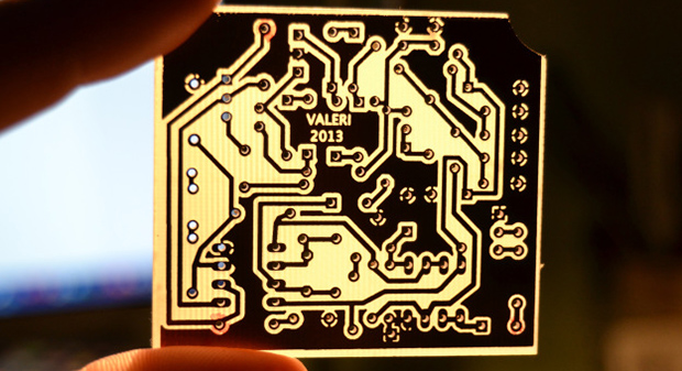
this image is an example. notice the holes are dead center of the pads in the upper left quadrant of the board while the lower right quadrant (and lower half for the most part) the holes are practically outside the pad entirely
are you sure this is all about squaring the machine? Michael mentioned how you could not concern yourself with squaring the machine by creating a square USING THE MACHINE and then placing your work in that square area.
But to me, those issues you are showing don’t look like out-of-square issues and look more like resolution or accuracy issues. Belts are tight? You calibrated your stepper motor movement and verified from both directions in both X and Y?
so if i image a 4inch square onto a piece of copper clad via my lcd/sla method, i need my machine to be able to accurately know exactly where the 4 corners are, or be able to trace the outline of the square (given a shared origin). at the moment my machine can come close but on larger square (like 200mm) it ends up being ever ever ever so slightly trapezoidal. i think that’s squaring, no?
If your axes are square to each other, then all you need is some true fiducial. If your board edges are accurate and precise, a template jig cut on the same coordinate system will solve your problem, as I suggested. If your axes are not square, then what you need first is to square your axes, or nothing will ever work right.
I’d suggest putting a sacrificial piece on the board and routing out a square as large as you conveniently can on your machine. Then you can measure whether it is square or trapezoidal (x and y axes out of square) and whether all the edges are straight and corners clean (backlash and slop).
We can definitely help with any of those problems. It’s just important to know what problems you actually need to solve.
The problem with having responded from my phone while doing errands this morning was that it was hard to see the big picture. But you really should post a picture, and if possible a link to where you purchased it from for more context.
Sounds like this machine has ball screws in each axis.
There might be some limitations from machine design. I think that a picture showing the mechanism underneath the bed might help.
In general, using two ball screws and two limit switches is a terrible solution; it can loosen over time due to racking forces while homing when it is turned on. So having only one ball screw isn’t bad — as long as the gantry is constrained to be square. This means that it really matters a lot what kind of linear motion system is in place on your particular router, on which the gantry rides, and by which it is intended to be constrained to be square to the direction of motion.
Anyway, I’d definitely start with machining a square. If you can put some acrylic in the mill, mark on it its orientation, and then cut out as large a square as you can such that the orientation is visible on the piece you cut out, you’ll be able to measure:
Trapezoidal distortion (gantry out of square)
Non-straight edges (imperfectly constrained motion, such as from loose linear bearings)
Accuracy in both X and Y
The reason to use acrylic is that it cuts cleanly (with a sharp end mill, anyway) so that your measurements aren’t confounded by bad surface finish. If you used polycarbonate the edge would be more likely to melt and deform and make your measurements suspect.
You’ll want a trustworthy square like a machinist’s square and a decent set of calipers large enough to measure your exemplar. The larger you make your exemplar, the more measureable any linear aberration will be.

 But you really should post a picture, and if possible a link to where you purchased it from for more context.