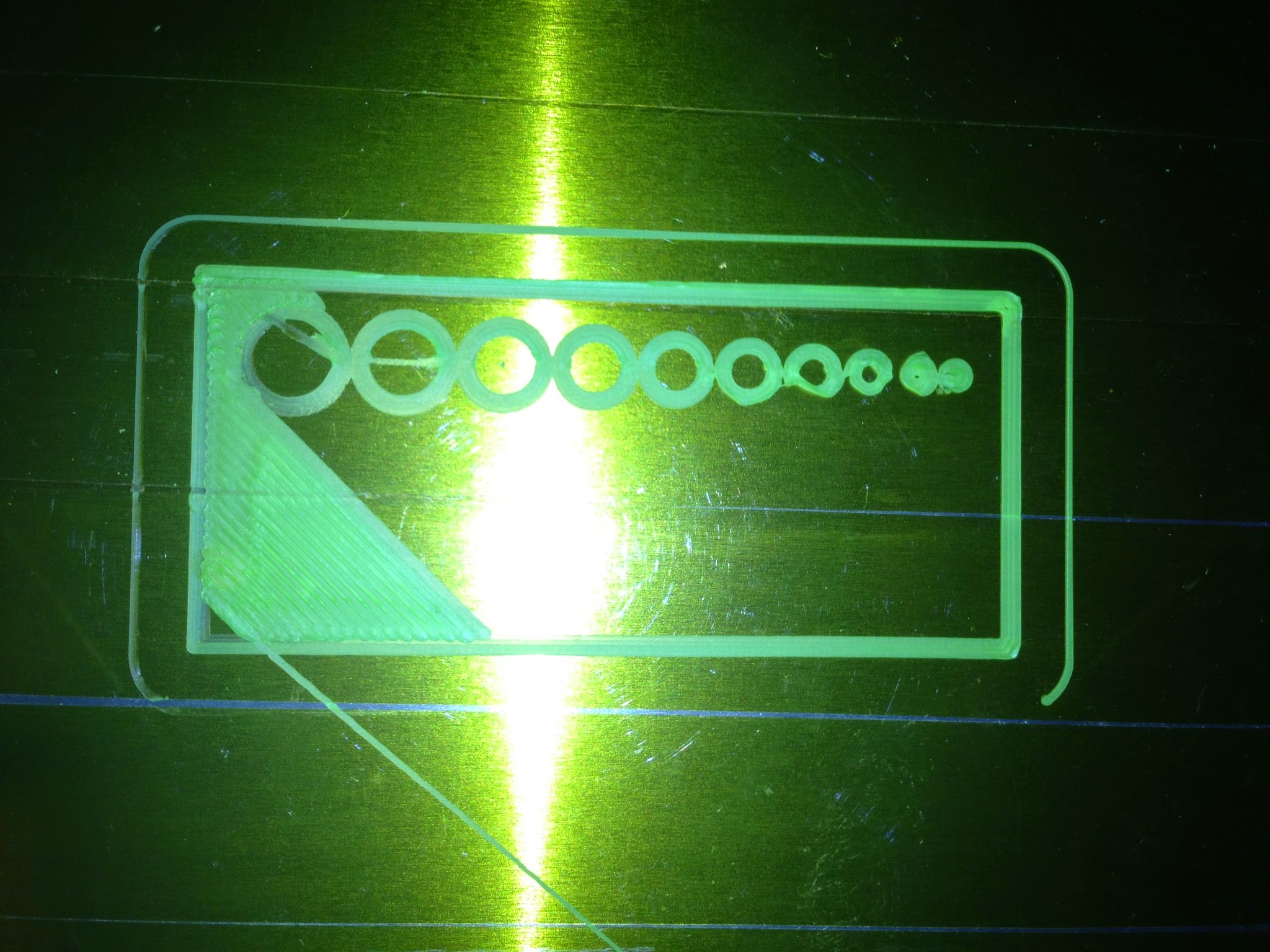
So I was sure that something was wrong when it came to the size of my holes so I made a block to see how accurate it could make it. I ended up stopping it on the first layer because I couldn’t believe how off it was. The holes start at 10mm and go down to 1mm. I measured the 10mm hole to be 8.88mm. What are the reasons this could be off. I calibrated it when I flashed the firmware. Any Ideas
You’re starting too close to the platform.
So my bed is to close is what your saying. You use a piece of paper right. I have a glass bed coming this next week because my build platform is warping around the edges.
There are calculations required to get the hole sizes correct. let me post them for you:
// This will size an outer diameter to fit inside dia with $fn sides
// use this to set the diameter before passing to polyhole
function hole_fit( dia=0,$fn=0) = dia/cos(180/(($fn>0) ? $fn : 0.01));
function hole_fit_poly( dia=0) = dia/cos(180/poly_sides(dia));
// This determines the number of sides of a hole that is printable
// I added +1 because nobody wants to print a triangle. (plus it looks nicer, havn’t tested printability yet.)
function poly_sides(d) = (max(round(2 * d),3)+1);
// Based on nophead research
module polyhole(d, d1, d2, h, center=false, $fn=0) {
n = max((($fn>0) ? $fn : poly_sides(d)), (($fn>0) ? $fn : poly_sides(d1)), (($fn>0) ? $fn : poly_sides(d2)));
cylinder(h = h, r = (d / 2), r1 = (d1 / 2), r2 = (d2 / 2), $fn = n, center=center);
}
Here’s a link to nophead’s original blog post.
Well worth a read.
Yup. My code above is based off of prusa’s code, which is based off of @nop_head I made my own changes to suit my needs, but so far I’ve seen people using my screw library which is based off this code and getting near perfect tolerances the first time. You will lose some tolerance due to how the perimeters are printed and squashed, however it’s typically within 0.2mm.
If you want to calibrate your holes, first calibrate your axis. There are several methods of doing this, however you want to calibrate over the largest area possible as that will make your calibration more accurate. Do the same for calibrating your extruder, then you only need the right nozzle diameter and filament diameter.
That looks to be for openSCAD right. I haven’t used that yet ive been using solidworks. I don’t think it has a place to put code in. Is openSCAF hard to use
You can do the calculations manually, you need to know the number of sides the circle has. Ideally you should set the number of sides, because above a certain resolution the printer actually over extrudes (see nopheads article for explanation).