Advice Requested Hello, I’ve been playing around with my basic K40 Laser for a while now. It has an analogue knob to control the laser power and I use inkscape and K40 whisperer for my designs.
I have removed the stock holder thingy and put in a piece of steel with nuts welded to it so I can modify the height manually using its “legs” ( bolts).
I also have a super simple air assist, basic aquarium air pump though so not very strong.
I love it, but of course it is imperfect
It is nigh on impossible to ensure I’m using the same power as I have done before, but a basic Google search shows that the digital controls are not accurate/sensitive enough.
I find that my laser is strong enough to cut with one stroke in the top left…but needs a lot more in the bottom right. (assumably due to the laser having to travel further.)
I would also love to be able to burn nice grey scale images into wood.
I was thinking of a Cohesion3D board would solve some of these issues.
I’m eager to hear everyone’s thoughts on this.
Does using this board limit what I can do in the future?
Does it control the power and such from my computer or do I still need to use the knob?
Can it auto increase power as the laser has to travel a further distance?
Does it/lightburn make grey scale images easy?
Any suggestions on a z Bed that the board can control?
The path that the laser takes along three mirrors and the lens needs to be precisely aligned. Here are three resources that may help you understand how to do this.
Note that if the third mirror does not align the beam with the middle of the lens, the beam will not be focused correctly and will not be aligned with the hole in the nozzle. You may wish to use a device that helps you align using a red visible laser. One kind uses a “beam combiner” that slightly reduces beam power, and the other is a tool used only while performing alignment .
I would check on the physical side first; whether you are on m2nano or c3d being able to adjust power consistently as the tube ages and getting alignment right is the foundation.
One of your questions is based on a mistaken understanding; increasing power by distance isn’t something you want; you want to fix alignment instead. For more details I’ll defer to other forum members, but figured this might help get you started.
Thankyou so much. I will level my mirrors soon :).
So my machine seems to have a analog ammeter on it. So to find the same setting I have used before I need to turn the knob and use the test switch? Wouldn’t that burn whatever I have in the machine? Is there anything I can put in for this that is safe? Able to not burn but also not reflect the laser back into the tube like metal would?
Congratulations on having a machine with an analog ammeter!
You can adjust the current by using the laser with nothing on the bed.
K40 Intro links to K40 initial setup and regular maintenance which shows a schematic of the light path through the lens. The lens focuses the beam, but below the work plane the light just keeps getting wider and wider, spreading the power out.
That’s the max power setting; then the software can set the total power in the range between zero and whatever max power you have set.
What do you mean the software can set the power? I thought the knob did that?
Or do you mean if I get the new board the software can go from zero to wherever the knob is set?
It’s good to know I can use the analog ammeter to know the power I’m outputting. But I’m still leaving towards the new board for the grey scale it claims I could do with it.
It was just luck I suppose, it I had known that there were digital ones out there at the time I probably would have brought that thinking it was better.
The replacement board you choose depends on your mechanical, electrical/electronic and software skills. The Cohesion3D board is a good choice and is almost future proof for a K40. It has the ability to add a rotary attachment at a later date. LightBurn of course is a wonderful piece of software for designing and operating the laser. In all honesty, you get what you pay for.
the knob to control the power is a variable resistor(POT) and when you turn the knob you are changing the wiper along a resistor and effectively changing how 5V is split across the two sides of the wiper. Think of it like 2 resistors where one gets smaller and the other gets larger as you move. So you can put a small compact volt meter on this POT and have a digital readout so you can always set your power to known previous settings without having to look at the amp meter and burn things.
Once you upgrade to a C3D, you will set this POT to the ~18mA setting and pretty much leave it there as it represents your maximum power. From then on, C3D will control your power level in software(LightBurn is great for this). When you tell it to use 100% power it will only go upto 18mA.
I have done this conversion and I still like having the volt meter so I can see how things age. ie as you tube ages you will need to up the voltage to get the same power output.
exactly. I’d originally put the volt meter across the POT back when I only had the POT and analog mA meter to adjust manually for cutting and rastering. Then I upgraded the controller and used LightBurn and it used to volt meter at a fixed voltage setting( 2.4V ) until my POT failed and I’d replaced the 1K POT with a 10K pot and had cutting issues. The feedback from the volt meter helped me see the problem was the 10K pot and the voltage was changing when the laser was enabled and a very slight change put on the circuit.
As my tube weakens and I find it no longer cuts 3mm ply at 15mm/s and 60% power, I will have to boost the voltage on the POT, the max power setting to the laser, which tells me over time my tube is worn out. I expect it won’t be but a few times adjusting the POT before either failure or it just won’t increase power any longer.
Just to be clear here: The c3d board has a great reputation. It’s a very reasonable choice for your system. It’s just that if you move directly to it without first fixing the mechanical issues you’ll be sad that it didn’t do what you had hoped, and it would be easy to not realize that the c3d isn’t the problem. That’s why I’m suggesting one thing at a time.
Meerk40t can do gray with the m2nano board, but I think it’s the only software that does that.
Cohesion3d brings plenty of benefits including four axes; you can hook up powered Z controlled from the board and also have separate A axis for rotary work if you would like that.
@Joanne_Bombardier I’m hoping that the tangents that this thread have gone off into haven’t obscured the advice. Alignment can be tricky work. If you find it hard to adjust the alignment, you might consider the American Photonics reverse visible laser alignment tool useful.
It’s not terribly expensive and can make alignment quicker.
Thank you all so much, this advice has been invaluable, I will be looking to properly level my laser and getting the volt meter before I get the new board, I will definitely going to get the board eventually and possibly the z table, but I’ll see how it goes for a while without.
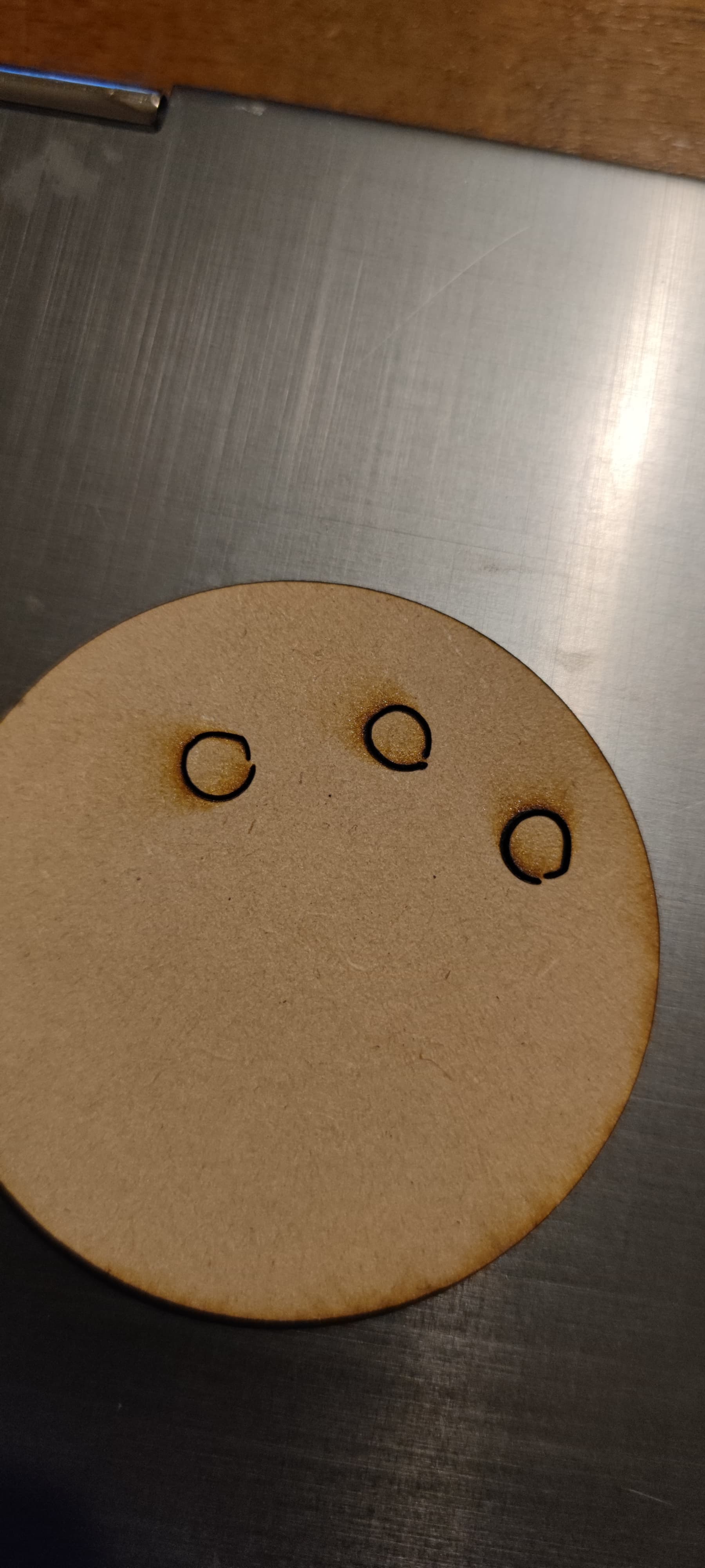
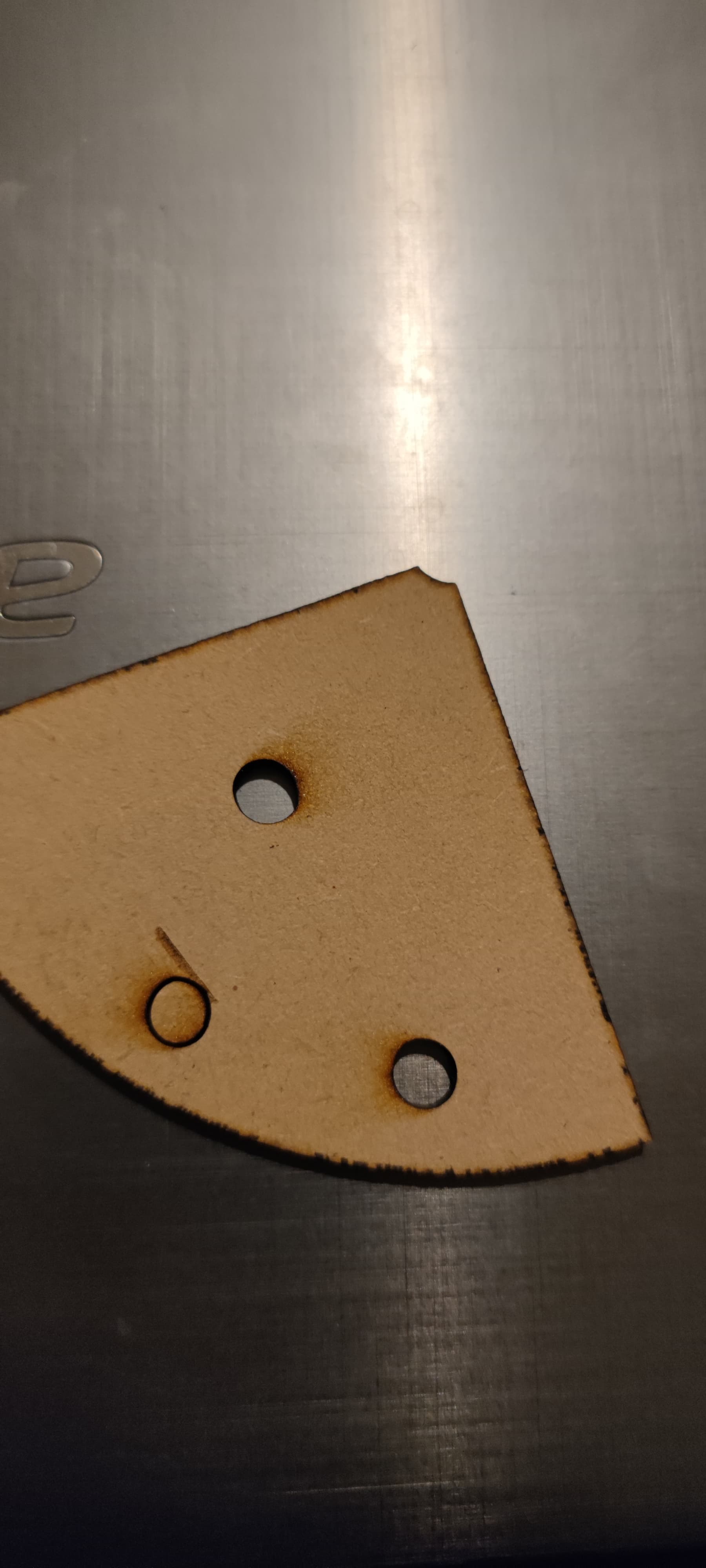
Ok I think I broke something. I’m hoping someone still has this set to watching.
I leveled the laser and it cuts soooo well. But now there is something wrong. I was test cutting circles. They are perfectly circular on my computer. But at the top left of my bed, they print wobbly and incomplete, and at the bottom right they are ovals. Please tell me it’s an easy fix