So I’ve got a problem with using my SBase board using the P1.23 firmware to control a diode laser. The laser driver and the Sbase board both use seperate power supplies(computer charger type). When I used this laser on an 8-bit board(GRBL on Uno), I used the boards spindle control pins with the lasers 2-pin PWM + and - to control output. I’m finding that connecting those 2 pins to the 1.23 pin and a ground pin doesn’t get me the same control. How can I use the SBase board to work with my diode laser?
The problem could be, that pin 1.23 only delivers about 3.3V (not 5V). This could be too low for your diode driver board. If so, you need to use a logic level converter (or transistor/mosfet) to push the 3.3V to 5V.
Awesome! I’ve tested the pin voltage. It doesn’t vary on my multi-meter, but I figure that it would be because because the frequency was way to fast for such a machine(It’s all I have. No oscilloscope). it is in the 3.5v range. Do you have any recommendation for such hardware?
so after reading this article, I think the 3.3v and 5v logics should both work on ttl devices.
any chance it could be something else?
Maybe I’ve got my configurartion wrong in LaserWeb4. I’m using GRBL levels of 0-1000 for the S value. Same in Laserweb. I know smoothie uses 0-1, and Uno uses 255. $32=1 as well.
It depends. And level shifters are super cheap and easy to use. From that article:
… a handy alternative can be made with a MOSFET and a couple of resistors. It’s also worth pointing out that this doesn’t have to be used on a bidirectional bus, it can serve as a general purpose level shifter for the cost of a 2N7000 or similar …
These level shifters are parts you can buy for $0.20 each for four-channel level shifters, $0.05/channel, in low quantities.
If the laser module needs current into the gate — say, if you are driving a BJT transistor rather than a MOS — that would be an example reason to use a level shifter.
Grabbed some level shifters off of amazon! I’ll find out Monday if that’s the issue. Also grabbed a power supply so that I can integrate it all together. Either way, I’m going to get it working!
Open drain mosfets configurations are a much better alternative than level shift-ers. An open drain driving twisted pair, pulled up at the destination end [or providing ground to an optical isolator] is a better method of interfacing between devices in a noisy environment.
Also make sure your supplies share the same ground.
@donkjr if this configuration was already working on a 5V supply on a GRBL, and quit working on a 3.3V supply on Sbase, no need for the complex solution. The MOSFET-plus-two-resistors level shifter is a cheap and easy way to get back to the status quo ante.
Obviously differential signalling is more noise-resistant, but even in audio short runs are often single-ended.
Open drain is not differential it is single ended. I think we are both talking about the same thing?
Not complex at all: mosfet, gate resistor and pull up.
Sorry, I read “twisted pair” and went too far. My bad.
But I was talking about something different in any case, the logic level shifter. It’s a MOSFET and two resistors which is sold in multiples and is practically a “popcorn” part now.
You are right these are different circuits.
Your circuit is typically used if you need bidirectional capability.
All that is needed is a mosfet switch configured as an open drain.
Most boards have these mosfets on board for driving spindles and such with PWM.
Instead of using the 3.3v signal directly from the internal pins, find a mosfet driver on board that can be configured as open drain and there will be NO parts needed. The configuration file may need to be changed.
@bsmith55 can use a mosfet driver that is on the board. I am pretty sure Sbase boards have these drivers.
The load end may need a pullup. The need for a pull-up will depend on what the input circuit on the diodes driver module needs.
In the unlikely event that an onboard mosfet cannot be found, add a driver module like this with a Mosfet whose Vgs(TH) is compatible with 3.3vdc: https://amzn.to/311SyZX
I hate to be that guy, but you guys are a bit over my head. I’ve gotten the level shifter, and am looking for the common 3v3 and 5v pins on the board that I can use to push the signal. I’m using a common 3d printer power supply(just got it). Will they be sharing a common ground by tying them to the same power supply? Or, will I need to run the ground from the PS to the SBASE, then through one of the terminals back to the laser driver? Sorry about this. I’m trying to learn, but I’m on a much more basic level.
Ground is shared signal ground, which should also be tied to the PS GND already through the board. You’ll need 3v3 and 5v supplies relative to ground. 3v3 reference voltage ought to come from the board, and input will come from the I/O pin you chose.
Connect 3v3 to the supply and P1.23 to the signal on one side of the level shifter, and 5v to the supply and the laser modules TTL in to the signal on the other side of the level shifter.
Ok, so I’ve got the logic level shifter(bi-directional) I’ve made the following connections.
LV + = j2.2(found it)
LV - = grnd(right above the J2.2 pin)
HV + = Aux1 5v
HV - = Aux1 gnd
channel1 input = P1.23
channel2 input = J8 Gnd
channel1 output = TTL/PWM +
channel2 output = TTL/PWM -
No laser control still. I’m so frustrated at this point. I’ve got the power cable/on-off switch coming in tomorrow, so I can hook it all up using a common PS, but for now, I’m still stuck on the two seperate wall chargers powering my rig. Where am I going wrong on this one? I’ve tested the output pins for both channels together and they are showing 5v, but the pins don’t seem to be turning of the laser at steady state. Is there an enable pin for the laser? should I be using S0-S1000 for the GRBL $30and$31? Thanks for any help on this. I’m desperate for this thing to work. It’s been too long trying with no success.
This is why I do not recommend and it is unnecessary to use level shift-ers.
Every time I have tried to help folks make this work it turns into a mess like this because it is to complex.
These shifters are not suited for a function like this and ground loops between supplies are always a problem. After you get this setup to work you will likely have lots of noise problems from the LPS.
Furthermore it is poor practice to bring the low level (direct from processor) 3v signals off the board, 3v processor signals will not reliably drive much of a wire.
You only need a pair of wires to go between an open drain and its ground on the MKS board to the L and gnd on the LPS. You do not need two supplies and you do not need a level shifter board to make this work.
I will look up the schematics I provided to other MKS users tonight. I think most folks used the “Bed” or “Fan” output to drive the LPS-L.
Unfortunately I have never found a schematic for these boards as they are smoothie clones that are not following the rules.
Thanks Don! Sure you can tell, I’m not much for the electronics side. I’m really into building the machines in unique ways, and have relied on simple 8 bit boards so far. Easy ±PWM spindle control for the laser. I had to wait on a power supply to integrate, but it doesn’t have a TTL plug, so I may have messed up. I’ll definitely wait for your post on the diagram.
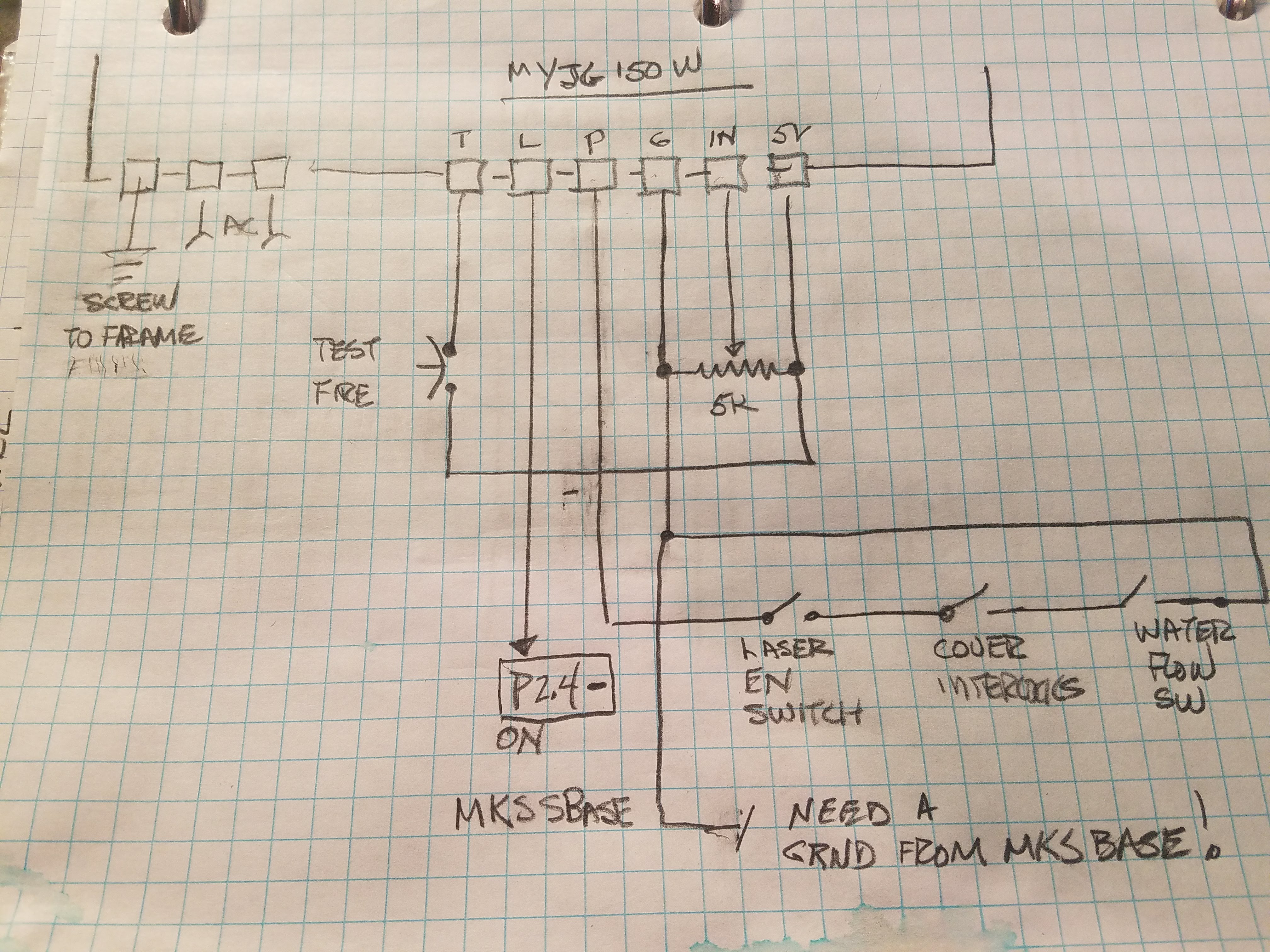
Here is what I dug up that helped others.
As I recall we used the fan output on P2.4 but I believe that the BED driver will work as well. We just need to replace the LPS with the Laser diode driver.
Do you have the specs on the Laser Diode driver?
To connect:
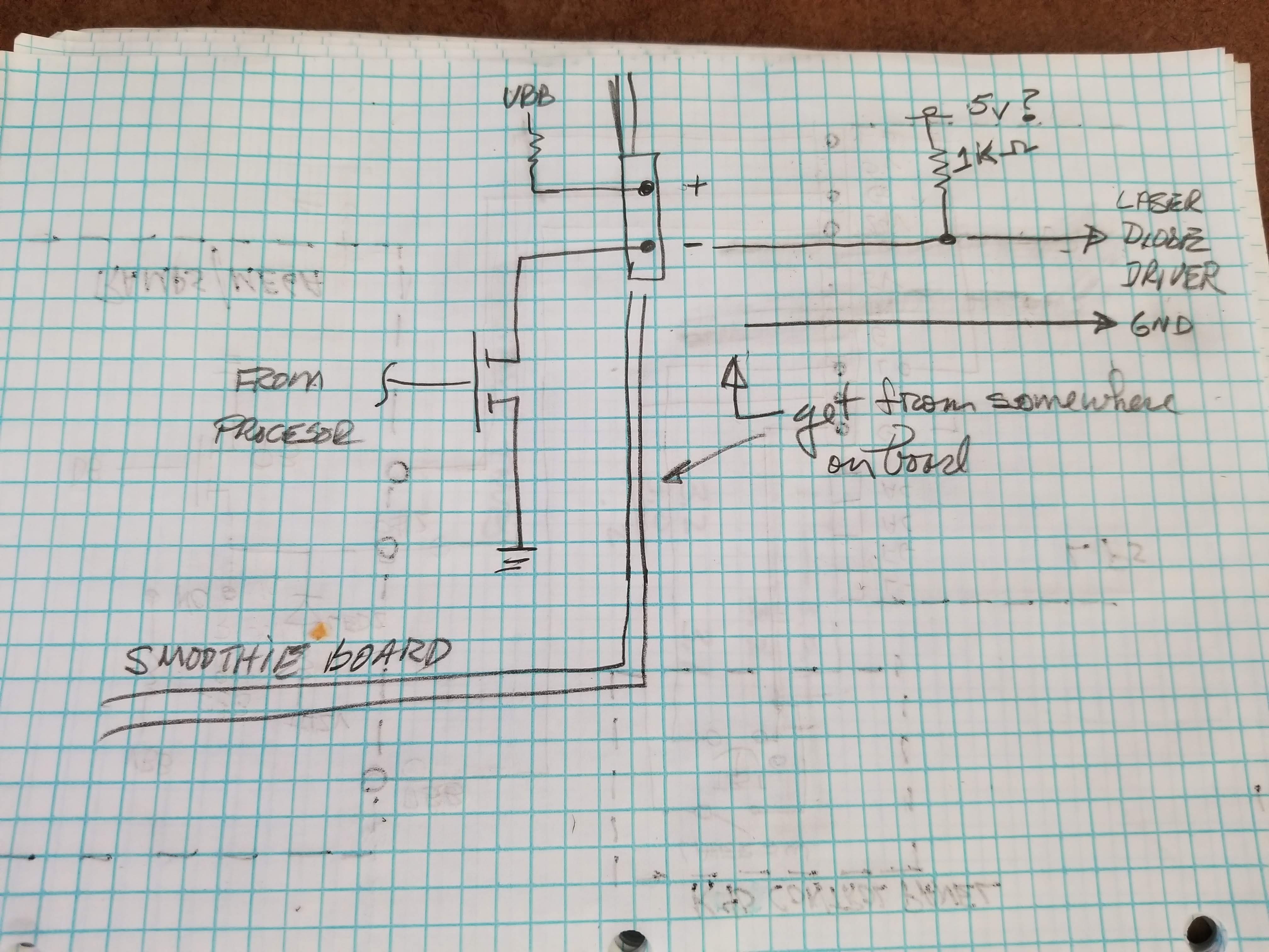
Connect the Drain of the output P2.4 FET to a resistor that is pulled up to 5V, 1-10K should be ok.*
Note: you can also configure a pull-up on the smoothie board to connect to 5V but I do not know how to do this on this particular board.
Usually the drain is on the - pin of the connector. The other pin (+) is usually connected directly or through a pullup to VBB. You can verify this by measuring [with power applied] with a DVM, each pin. The one that has VBB voltage on it is NOT the one you want.
Find a ground on the smoothie board and connect it to the ground of the diode driver.
Configure P2.4 like this in the laser module of the config file:
laser_module_pin 2.4 # this pin will be PWMed to control the laser.**
Caveat 1: I am guessing that the PWM input of your laser driver is TTL or 5V compatible.
** Caveat 2: I am assuming that the LED driver is expecting a low true signal if not the pin can be inverted in the laser_module_pin definition
*** if the laser module is expecting a ground then the pullup can (and may need to) be removed.
@donkjr Be aware that he has a diode driver, not a LPS. This driver needs a positive TTL PWM signal. And he is using grbl-LPC (not smoothieware!), which doesn’t have the option to invert the PWM signal by software.
Therefore, the easyest solution is to use one channel of the level shifter to convert the 3.3V pin (p1.23) to 5V for the laser diode driver. The level shifter is nothing else than a n-channel fet with two pullups.
@bsmith55 Warning: Make sure the MKS board is powered before the HV (higher voltage, 5V) of the level shifter, or the laser will fire with 100% power (because of the pullup to HV). An easy solution is to add a toggle switch to the HV pin that connects to either GND or 5V. This way you can manualy deactivate the laser by switching to GND.
Guys thanks for all the help! I went with the regular mks sbase firmware and that fixed it. I think my 1.23 pin was bad. Used an Arduino to make an osciliscope and got nothing but open voltage 3v3. Switched to the mosfet and used it on the ground pwm pin and the 5v pin from the sbase and the whole thing came to life! Osciliscope read a beautiful signal from it. I’m so glad it works. GRBL LPC us such a fantastic upgrade! It’s much smoother and faster than my 8 bit boards. Now I just have to figure out this tool chain thing so that I can drive my dual y axis with individual drivers. Running them in series right now, but I’d like to split them. Off to the YouTube! Thanks again everyone!