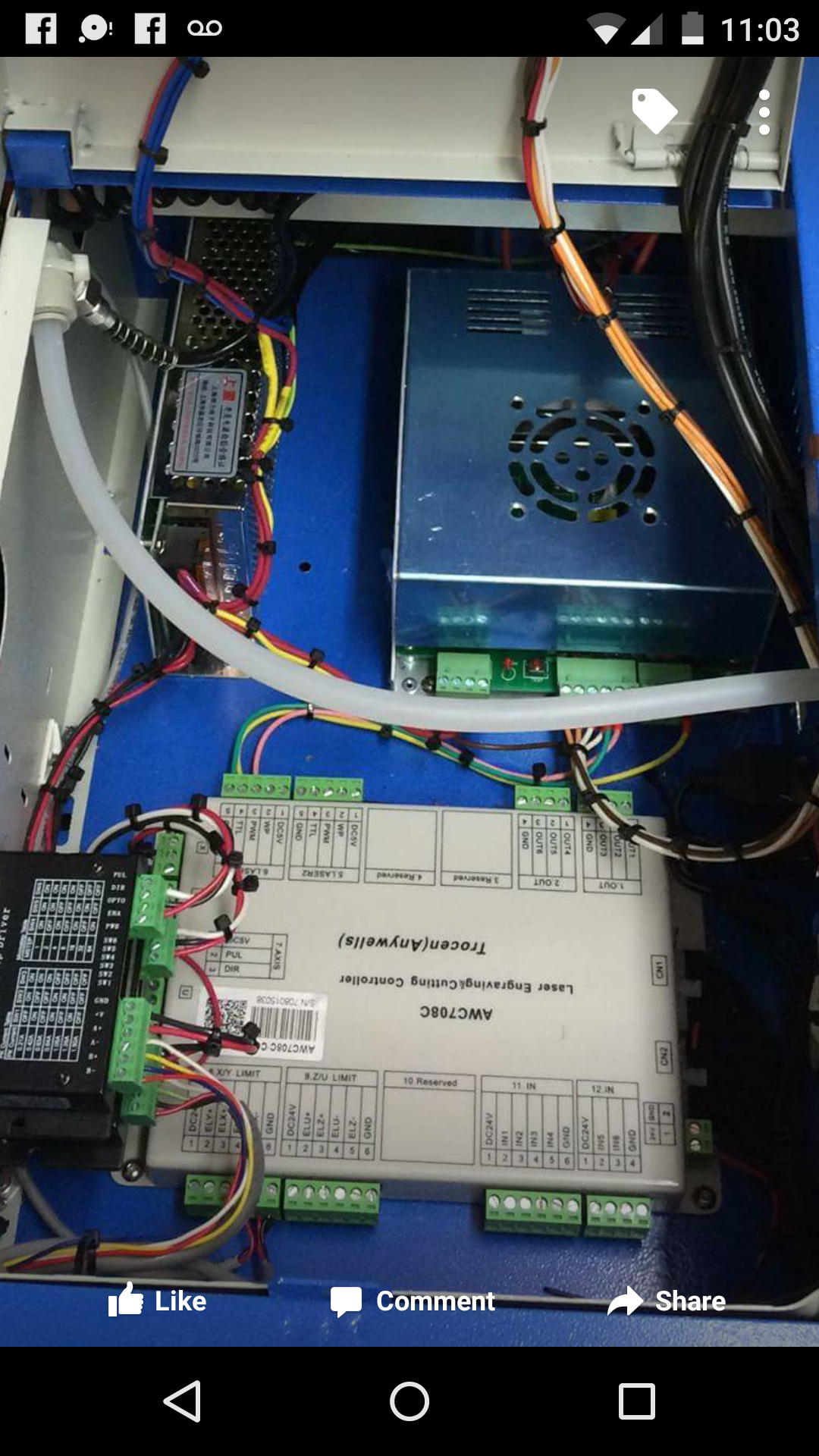
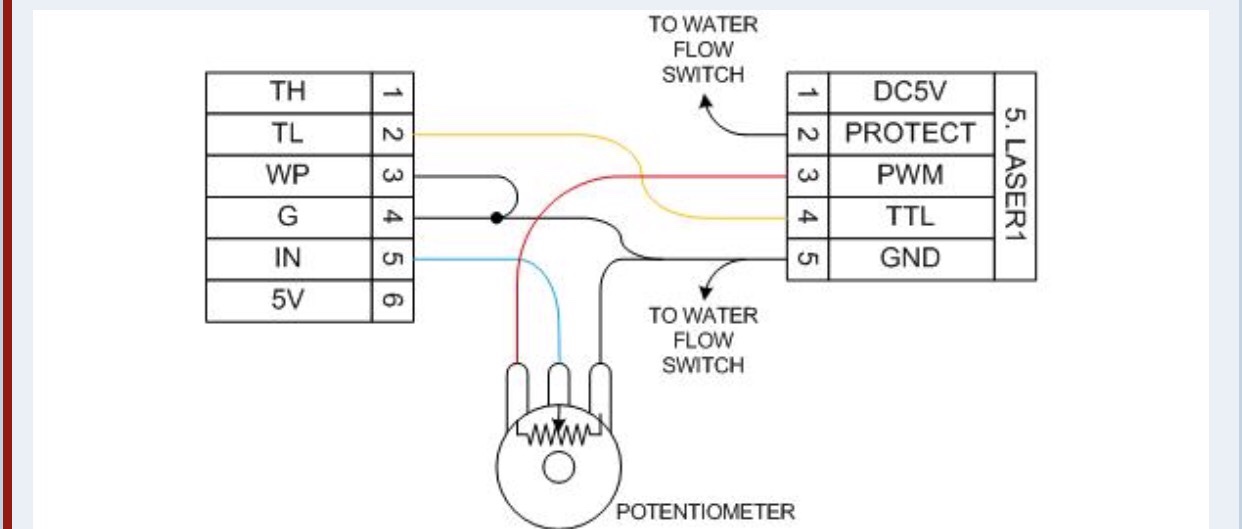
Saw this DSP upgrade on Facebook looks as if they are TTL on In and pwm to the Pot connection… maybe useful for figuring out the best way to wire up a smoothie conversion
Thanks, part of my research was to understand how LO interfaces their controller to the LPS. They have connection diagrams on their support site:
Interestingly they do it two ways:
In one case they ignore the L and use only the TH and IN even though all three are present. I think in some supplies TL and L may be connected internally. In the one I have been tracing L is connected to the enable signal usually used for enable and interlocks.
In the other case they use IN and L like above.
The most relevant learning from this is that this works with no level shifter which makes sense cause the LO DSP’s don’t provide 3V outputs.
My big aha this week was that folks are taking the PWM signal from the boards internal PWM not through a FET :), which is why a level shifter is employed.
Soon this will all be clear and crisp…
+Peter van der Walt Kim is using a power supply from light objects if that helps you
+Peter van der Walt LO recommends using IN (PWM) and ground, but I couldn’t get that to work. I’m now wondering if I needed the L as well to fire. I’m using 5V/L/G right now, but I have yet to get what I would consider to be a successful engraving of an image w/ lots of grayscaling.
+Peter van der Walt Can you point me to (or summarize) the theory of how “PWM” engraving works vs vector. I assumed that while engraving the PWM was continually adjusted at the pixel level whereas vector set a certain pwm value for a full line segment.
Things that I think would impact engraving and might be invisible in vector:
If IN is not at 5V the LPS is not running at 100% power even if the smoothie PWM control is at 100%. In this case the external control is really not fully controlling the supply.
If IN is at a voltage other than 5V the effective control of the power is the product of the IN created DF and the smoothie PWM DF.
Insure that smoothie PWM signal as at the right polarity and fully transitioning from 0-5V.
The essence of the above = keep IN at 5V.
I would also imagine the frequency of the PWM would have an effect on the engraving if it is to low a frequency relative to the frequency that the PWM value changes.
What I have found in tracing these supplies is that they have three basic control functions internally. All inputs connect to one or more of these generic functions.
The confusing reality is derived from the realization that that multiple combinations of these signals can be made to work. For example I think you could pull L low, IN high and PWM an enable signal and it would work.
Simplified theory of how the LPS internals work:
Enable: either enables the internal PWM to run or enables the PWM control to adjust the internal PWM DF >0.
Fire: enables/disables the output of the internal PWM and therefore the output of the supply.
PWM control: adjusts the internal PWM and therefore the supply.
Likely intended uses for these signals:
Enable: interlocks and other signals that enable-disable the laser from firing no matter the other inputs.
Fire: turning the laser on and off when Enable is asserted and at whatever power level is set by PWM control.
PWM control: analog setting of the power by adjusting the internal PWM from an external control (like the pot).
The other realization that I had is that there are two “PWM’s” at play in a controlled system, depending on how you configure the external controls. One is the PWM asserted from smoothie and the other is a PWM internal to the LPS.
I concluded that these two PWM controls are redundant. If the smoothie is going to have complete control of the power the internal PWM should be effectively set at 100% if full power is expected, for each external PWM pulse .
@K1111 my answer to “why to pins” would be that with a two pin configuration you have control of:
- The supply’s output with one pin (in this case TL) independent of any other control.
- The supply’s power level with the PWM dependent on #1. (however in the case you show above the power level is the product of the pot and the external PWM)
So if you want a control that overrides everything you can control enable (TL) to the smoothie as a separate signal. BTW not all supplies have TL, TH.
If the smoothie only asserts its PWM when it expects the laser to be on then #1 is theoretically not necessary.
However, If you wanted more control independent of the controllers PWM then asserting #1 at the start and end of a job would provide added overriding control of the lasers output?
To my thinking the “Laser Switch” provides enough external override for safety.
@donkjr So when I run the above configuration: PWM to IN, Pin 0.26 to L (on/off), G to G, it works, but the pot is weird. I can’t use the test fire button at all, and the pot will turn the current on and off just by turning the knob. I can set turn the pot until the laser starts to fire, and if I run a job while the pot is causing the laser to fire, the laser turns off and doesn’t come on. Once the job is finished, the laser will turn back on until I turn the pot down to turn it off.
If I take the pot out completely I get a max mA of maybe 10mA.
+Peter van der Walt Ok. I was thinking that I could avoid the shifter if I went to from 2.4 to IN since I was bypassing 3.3v on the board all together.
+Peter van der Walt So 2.4 on the board to 3.3v side of shifter to 5v side of shifter to IN?
+Peter van der Walt I haven’t spent much time researching but how do access these new functions on the LCD?
+Peter van der Walt Thank you!I didn’t have that firmware loaded, just the standard. Having that Laser option on the LCD is great!
+Peter van der Walt mmm nothing happens when I press the encoder shaft?
+Peter van der Walt After installing the CNC firmware, homing from LW takes me to 0,0, where as homing from the LCD takes me to 0,250, which is where I want it to be. The laser also doesn’t turn on now when a job is running. My config file is the one pulled from the X5 folder on the smoothie git hub page. Is it possible it’s meant for a 3D printer, and that’s why I’m seeing the difference?
G28.2 is your homing code to use with the cnc firmware