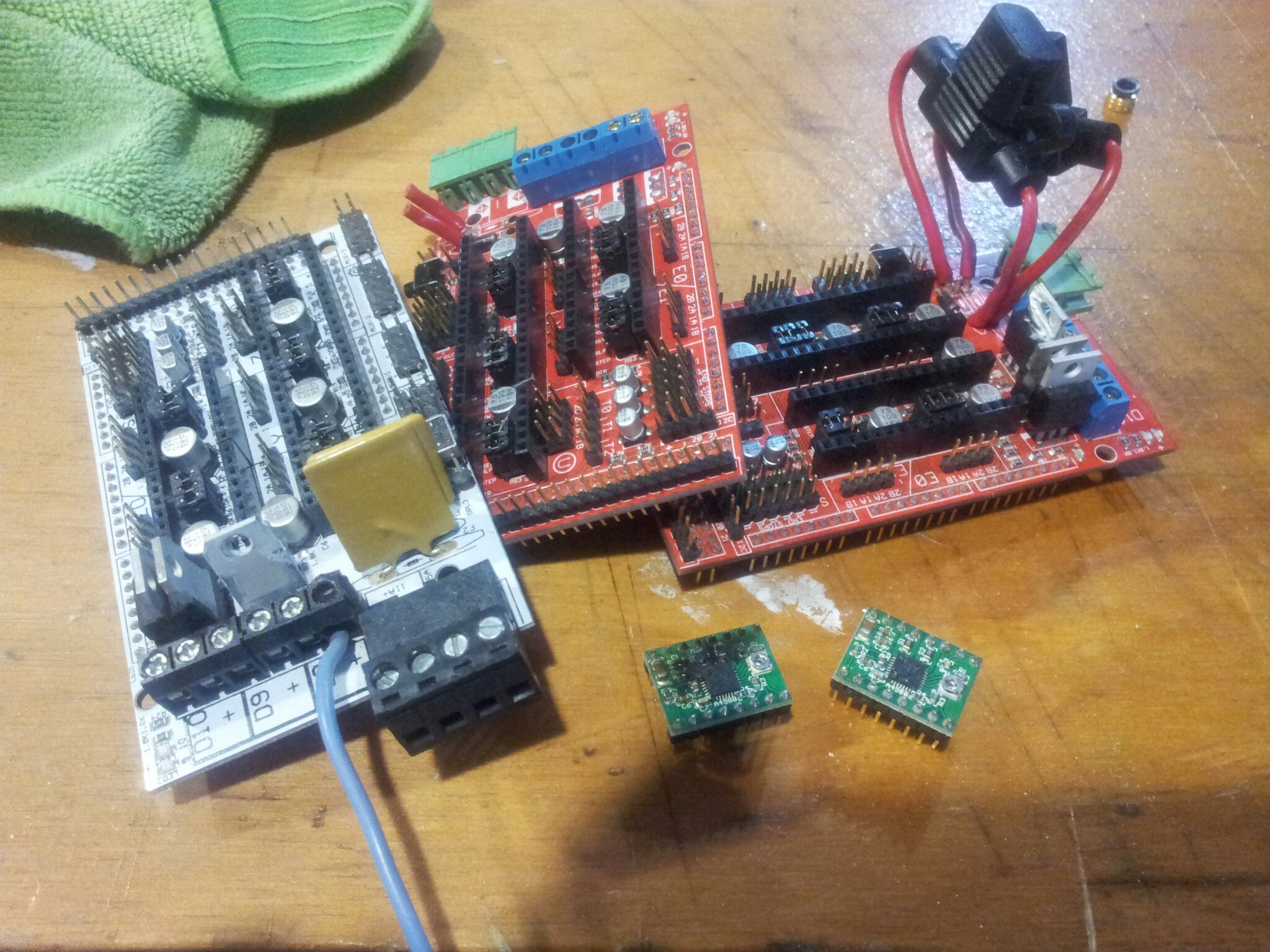
I’ve said it before: RAMPS are pretty hard to kill. They’re basically just traces and caps. Maybe you can replace a cap or two? Drivers die easily (is that one actually burned!?).
Also: I would really appreciate more info on your misadventures. Some of us are looking to convert the 24V RigidBot to a generic RAMPS setup.
I run my whole system on 24v. Why not run at 24v? If it’s a 12v bed I can see the problem. But then again I am running an Azteeg x3 which is a really robust board. I have no experience with ramps.
Looking closer, why do the two red ones still have D1 in place? I thought that had to be removed to run at 24V so that the Arduino Vreg didn’t get over-volted.
I run my heated bed (normal 2B with 24V connection points) at 30V by using a solid state relay and a separate PSU. It is simply awesome, I can heat it to 120C in 5 minutes now, where it would take 30 minutes to get to 110 before.
@Carlton_Dodd yes, there was a real flame inside my box emanating from that driver. Hindsight is that I didn’t down adjust the trimpots when upgrading to 24v. I think that’s the cause of the fire.
As for d1 resistor, it is removed in at least three of my dead boards, some of these are historical failures.
The white board failed due to resistive overheating on the heated bed connector from a poor connection and poor design of the rostock max. (The ramps mounts on the door so all the wires get jiggled when inspecting things)
The middle board failed because I overheated the traces in my extended attempts to install blade fuses. (Yeah yeah, 500c is too hot… yadda yadda)
The third one probably still works now that I’ve replaced the bed heater mosfet but I tossed it aside while trouble shooting the y not working. In the end it turned out that my fire on the extruder driver blew out the mega output pins that control extruder zero. I switched my firmware to use ext1 instead and all is well.
Cheap RAMPS generally don’t have PPTC fuses that work with 24V.
24V doesn’t involve changing the pot settings because the stepper drivers automatically compensate - driver chips are current based operation, not voltage based. It’s possible the drivers had other parts that were cheap that weren’t up for the task.
I think cheap FETs are more likely to work well with 24V operation but only if your heaters are reworked for 24V. Using 12V heaters at 24V is a recipe for trouble for the heaters and the FETs.
Sooo, converting from a 12V rig to 24V isn’t such a straightforward process.
@3D-Proto That depends on your Mega. If you have an authentic one you can handle up to 17V but above 12 isn’t recommended. If you have a Mega clone look up the voltage regulator’s max operating condition. The max on my taurino classic is 15V so I’m keeping it at 14.
I did 28V using an Ultimachine RAMPS, an MK2B heated bed wired to 24V setting and a heater cartridge chosen for 24V operation. I had 24V fans on that too, I should have put the fans on a power regulator because it ran too fast when overvolted. All parts were designed for 24V use, except the Arduino Mega had a separate regulator to keep it safe.
Read the caps on the board and see if they are rated for less that 24v (in which case do not put 24v to them) or more - in which case you are fine. Bed heater and cartridges also have to be 24v capable, and the arduino needs to be run through a transformer putting out not more than 12v as do the 12v fans. Done this a couple of times with great results so far.