Root 3 CNC - MKS DLC V2.0

I didn’t ever connect the endstops in the first iteration of my OX, but I’m planning to wire them in as I rebuild so that I can recover if I move the spindle while changing bits, because I did run into that a couple times earlier, and while I fudged it then I’d rather not have to.

Also the soft limits only work if you also have limit switches to home to.

2 Likes

+1 for repeatable end stops. Being able to resume after a snafu routing or milling is a godsend when you need it.

2 Likes

Wired end stops it is then.

Not sure how much I should set the acceleration to.

Should I increase the max rates?

$0=10 ; Step pulse time, microseconds
$1=255 ; Step idle delay, milliseconds
$2=0 ; Step pulse invert, mask
$3=6 ; Step direction invert, mask
$4=1 ; Invert step enable pin, boolean
$5=0 ; Invert limit pins, boolean
$6=0 ; Invert probe pin, boolean
$10=1 ; Status report options, mask
$11=0.010 ; Junction deviation, millimeters
$12=0.002 ; Arc tolerance, millimeters
$13=0 ; Report in inches, boolean
$20=0 ; Soft limits enable, boolean
$21=0 ; Hard limits enable, boolean
$22=0 ; Homing cycle enable, boolean
$23=0 ; Homing direction invert, mask
$24=25.000 ; Homing locate feed rate, mm/min
$25=500.000 ; Homing search seek rate, mm/min
$26=250 ; Homing switch debounce delay, milliseconds
$27=1.000 ; Homing switch pull-off distance, millimeters
$30=1000 ; Maximum spindle speed, RPM
$31=0 ; Minimum spindle speed, RPM
$32=0 ; Laser-mode enable, boolean
$100=44.730 ; X-axis steps per millimeter
$101=44.730 ; Y-axis steps per millimeter
$102=400.000 ; Z-axis steps per millimeter
$110=7000.000 ; X-axis maximum rate, mm/min
$111=7000.000 ; Y-axis maximum rate, mm/min
$112=5000.000 ; Z-axis maximum rate, mm/min
$120=20.000 ; X-axis acceleration, mm/sec^2
$121=20.000 ; Y-axis acceleration, mm/sec^2
$122=10.000 ; Z-axis acceleration, mm/sec^2
$130=200.000 ; X-axis maximum travel, millimeters
$131=200.000 ; Y-axis maximum travel, millimeters
$132=200.000 ; Z-axis maximum travel, millimeters

Max rates of 7000mm/m = 116mm/s = 275in/min. So that should be plenty for any realistic routing you would need.

But 20mm/s^2 is a ridiculously low acceleration. For my R7 CNC I use 400mm/s^2 and that is lead screw driven.

$130 to $132 should be set to your machines max travel distance plus a tiny bit. They only apply if you use soft limits I think.

3 Likes

Are you saying I should be able to go above 400mm/s^2 for acceleration since I’m running a belt driven system?

I would start bumping it up until you have problems, then back it down. That’s the only way I found to accurately get your machines limitations is to slightly pass them, then give yourself a safety margin.

When I found $$ time, everybody. What are your GRBL settings? from immediately before the gpluscalypse, I was surprised by the 10mm/s acceleration entry in it. I went really conservative at 100mm/s and ended up never pushing it to see how hard I could accelerate.

That squeal makes me wonder if something is on the edge of binding, though!

I think I lost the squealing noise. :grinning:

When I have the acceleration set to anything over 100mm/s^2 I’m not visually seeing a difference. When it is set to 50mm/s^2 I can see it accelerate. I had it set to 1000mm/s^2 but it acts like it isn’t accelerating.

50mm/s^2:

100mm/s^2:

1 Like

Maybe I should just run some test gcode and check the timing it takes to complete with different acceleration speeds?

You’ll see the difference more with smaller moves of course.

1 Like

I need to wire this up to 220V. I’d like to get it right the first time. :exploding_head:I don’t normally wire anything up to 220V. I will have a ground, neutral, and two hots right? Where do I lay all of those 4 wires down here? What size wire will I and breaker will I need?

This is the spindle I’m using:

The wiring from the inverter to the spindle seems to be shown below:

A bit of background: Nominal 220V is European (and other countries) standard where one leg is hot 220V RMS (316V peak) and the other is a neutral leg. Nominal 240V is American (and Canadian, and a few other countries) where both legs are hot and each leg is 120V RMS (172V peak) relative to a neutral (which might not be run to the outlet) but they are in opposed phase, so between them they are 240V RMS (345V peak). Fortunately, nominal 220V ranges between 220V and 240V depending on country, so it’s generally OK to use worldwide “220V” equipment with US 240V power.

This difference between systems means that “L” and “N” are misleading when using equipment marked for nominal 220V on a US 240V system. In Europe, the would be 220V load and neutral, but in the US they are both hot, and there is no distinction between them. I’ve often seen them designated “L1” and “L2”

Fortunately, voltage is only a relative thing, so as long as equipment doesn’t care about a difference between neutral and ground — and most doesn’t — what it sees is 240V RMS between “load” and “neutral” so it doesn’t matter.

A lot of US-centric devices use GND for the supply, but many others differentiate betweeen GND as a DC 0 voltage reference and PE for “Protective Earth” for the ground line in your power cord that is actually connected to earth at your house.

Most 240V outlets have only two hot and one ground. There are a few that have a neutral as well, but that is usually because they are meant to feed something that needs both 240V and 120V supplies, or to feed a sub-panel. Electric range outlets are one example of this; modern US code requires range outlets to be 120V/240V four-prong style and modern ranges may take advantage of both. By contrast, electric dryers and EV chargers typically don’t have a neutral wire at all. Most 240V outlets are three-conductor; L1, L2, and ground.

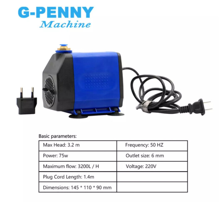
My 240V CNC OX has only two hot and ground. I got a 240V CW-3000 so that I could put it behind my e-stop with the spindle, so that one of the emergencies I could stop with the button would be water spewing from a broken coolant line. If I were using a 120V CW-3000 as a cooler, I would have had to have run a four-conductor supply, and put the cooler on one hot leg and the neutral line. This means that I’m running both hot lines through my e-stop, which is a dual-pole device.

When you wire up 240V, never use an unmarked white wire to carry one of the legs. Unmarked white wire must be neutral, never hot. This is a safety consideration. If you need to run a hot leg across a white wire, both ends must be marked; normally by wrapping a few turns of black electrical tape around them.

Therefore, make sure you mark your white wire, and then your two load wires (typically called “L1” and “L2”) will connect to L and N.

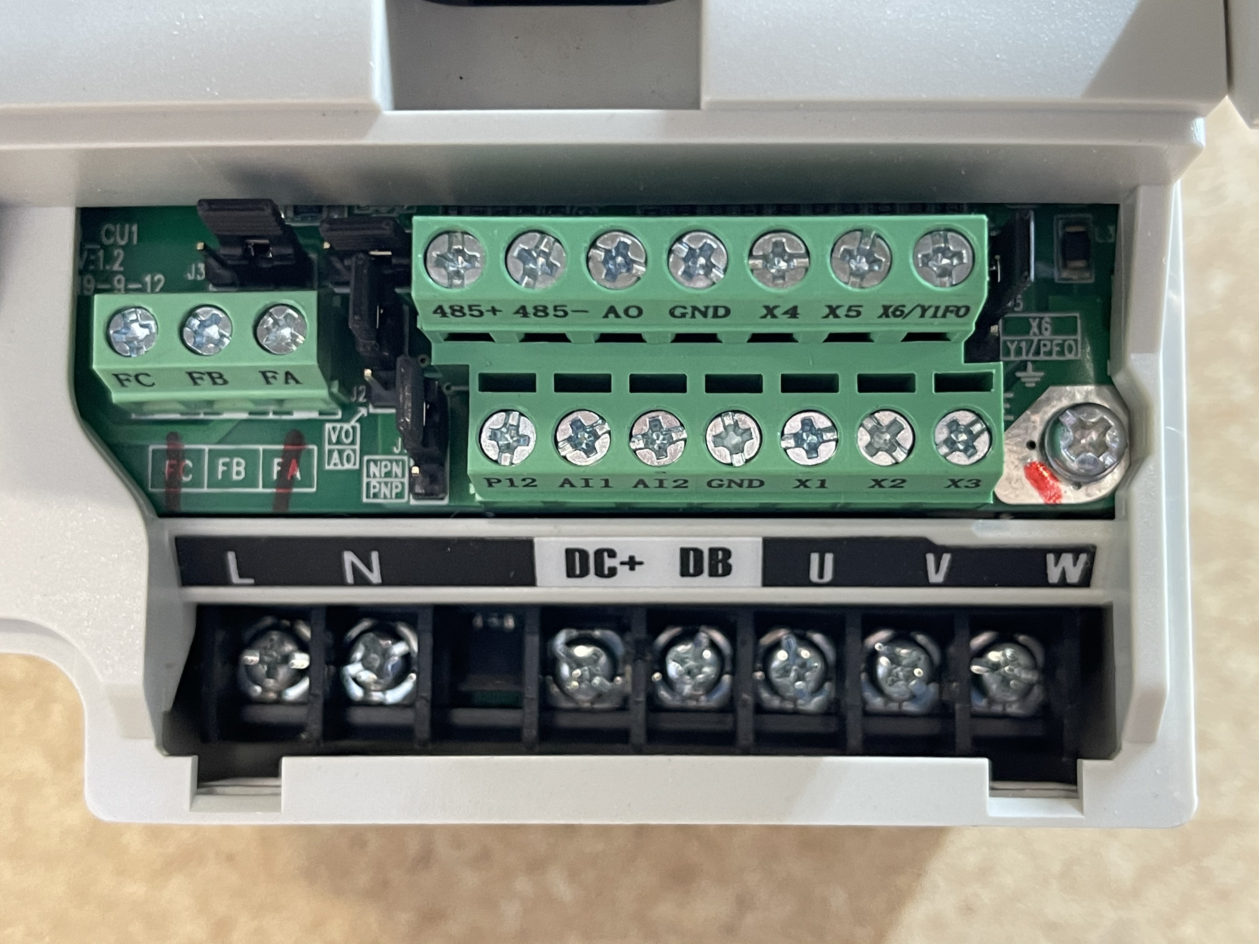
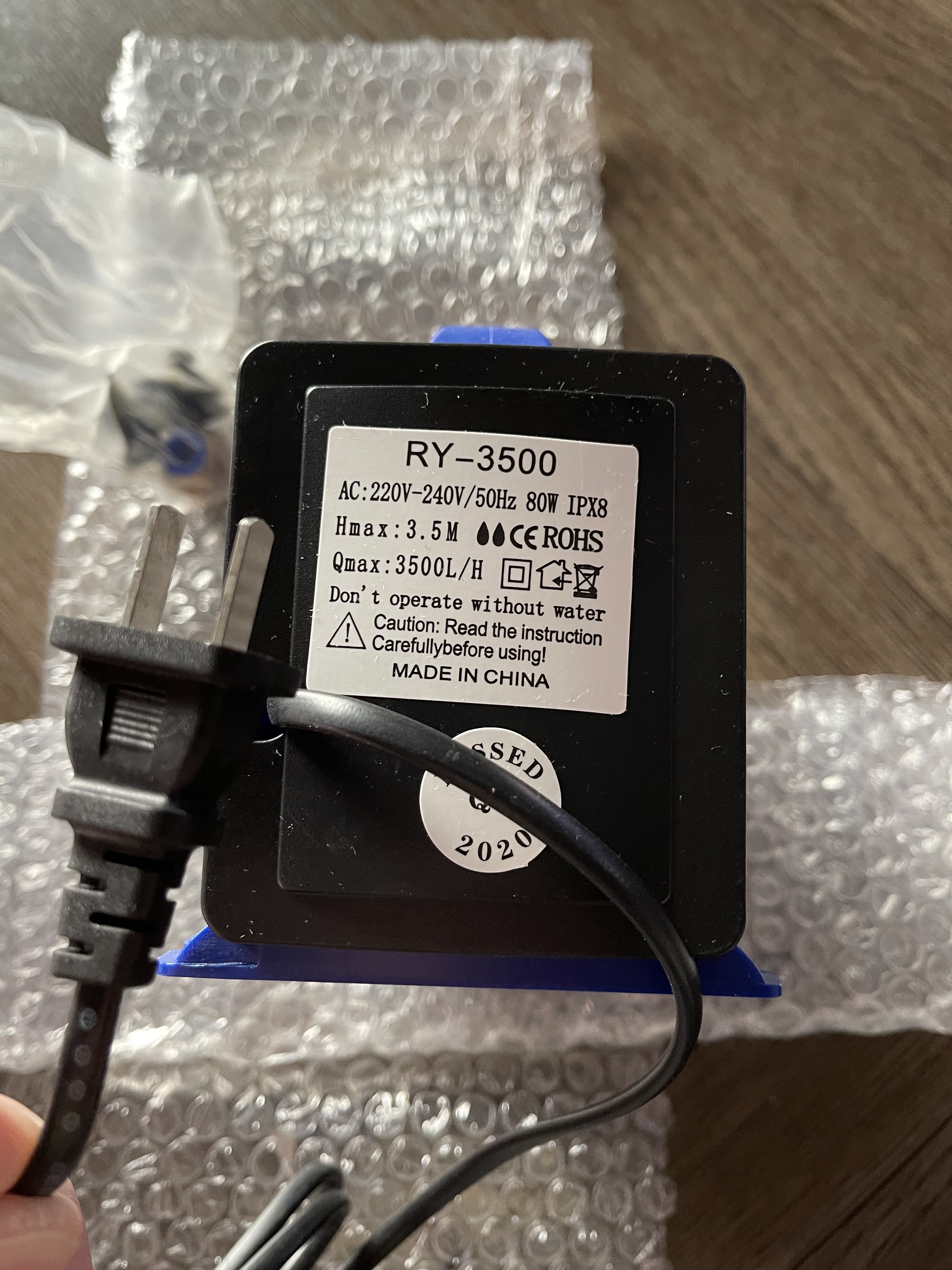
I don’t see a terminal labeled “PE” in your picture, but the big screw on the right side of the circuit board with the red mark next to it looks like it is meant for the PE connection. (I would have expected it to have been a screw terminal on the bottom row but I guess they cheaped out on that.) Don’t just screw a wire into that; use a crimped ring (or spade) terminal. You’ll have two terminals because you’ll also be running a wire to the ground connection on your spindle from the same screw.

Use ferrules for all the other wires that go into both styles of connector otherwise to protect against wires breaking.

If you are trying to wire all the way to the breaker and not just to an existing outlet on the wall, it gets complicated. Gauge of wire depends in part on the length of the run. But it also depends on what outlet you use. I don’t know how much power your pump uses, but 2.2kW is about 10A at 240V, which is much less than any 240V outlet you buy. You must size the breaker to protect the weakest downstream component. So you could put in a 30A outlet and wires that could carry 20A and put a 15A breaker behind it and be safe, but if you put a 50A breaker and wires sufficient for 30A and a 50A receptacle that would be a fire hazard. You will need a dual-pole breaker with the poles tied together. This will use two adjacent spots in your breaker panel.

So just to be clear here, are you planning to run wire through the wall for this on your own?

2 Likes

From the circuit breaker panel to my Root 3 CNC it’s about 6 feet.

I was planning on just running the wire out the circuit breaker panel to my H100 Inverter with the emergency stop somewhere in between.

Looks like the output current is 17A. (Not sure on the model I have at the moment)

Well crap I was thinking the water pump was just a standard 110V pump but it is 220V.

Will I need two separate breakers now? Maybe I should just wall mount two outlets on the wall for this.

I am not an electrician, nor am I an electrical engineer. I have read code and have done my own electrical work from time to time, and I have identified mistakes made by electricians in my home, but this does not qualify me to give advice here. I’ll give you my best understanding based on the information you’ve shared, but don’t trust me. Validate it. I’m trying to help you orient yourself to get better information from reliable sources; I don’t replace an electrician!

Also, “code is written in blood” but for electrical code it’s more written in charred flesh. The rules in code are based on preventing things that have gone wrong in the past from going wrong again. With electricity, that’s electrical and fire safety both.

Keeping that in mind, I’ll try to say useful things.

A 20A breaker would be sufficient to run both.

That’s a good thing! It means you can have one e-stop for both. Why wouldn’t you want that?

If that pump uses a synchronous AC motor, it will pump a little faster because it’s designed for 50Hz and you’ll be running it at 60Hz.

You can hard-wire without an outlet, but to my recollection code is different in that case; I think you end up needing to know both national and local electrical code to do that right. I would use a receptacle.

You can put both the spindle and the pump behind a single e-stop, as I did, and 20A will be sufficient for you. A 20A breaker can be used with 12AWG wire in your case. (10AWG is required for 30A, but you don’t need 30A.) In my case, I also have a 24V power supply for the steppers behind the same e-stop.

I would install a 20A tied two-pole breaker and use 12/2 NM-B W/G or 12 AWG stranded wire in conduit (depending on code requirements) to a single 240V outlet (I recommend twist-lock NEMA L6-20R), then use 12AWG SOOW (or similar) W/G wire from the L6-20P plug to an enclosure on the router with the e-stop, and then from the e-stop I would hard-wire to the spindle controller and cooling pump with 12AWG stranded wire. Use appropriate strain relief and/or cable grommets as necessary to protect against fraying.

I don’t know details of how far building code goes when you hard-wire appliances.

At least if you hard-wire, I think that code might require you to have a second circuit breaker for the pump if its wire is (as I guess) smaller than 12AWG. This could be downstream of the e-stop, it doesn’t have to be in the panel. All the wire downstream of a circuit breaker (or fuse), at least as far as the next breaker or fuse, must be sufficiently thick to avoid overheating at the maximum rated breaker (or fuse) current. This is to protect against fire. You should put a circuit breaker or fuse between the e-stop and the pump even if it’s not hard-wired; it’s still a fire safety issue. I don’t think building code applies when it’s not hard-wired, it is just good sense to protect against fire. An inline glass fuse is cheap fire insurance. Should be a few bucks for a 5x20 or 6x30 inline fuse holder on amazon or ebay I’d think. Last project where I needed something like this I think I bought two dozen of them. :smiling_face:

Your aliexpress link was to the 2.2kW unit and there it says 10A. Here it says 11A. Either way 20A is going to give you plenty of headroom.

Here’s something I wrote up a while ago for someone else who was wiring up a mill, in the same vein of sharing understanding without being licensed in any way:

1 Like

Wow thanks for the information. I went and got some parts to wire it up. Taking a nap currently sounds like a better idea. :grinning:

This can’t really be 220 volts can it?

Well, it’s clearly the wrong plug for 240V in the US. The question is whether it can run on 120V or simply has the wrong plug. Have you asked the vendor? I’ve had multiple good experiences asking questions of vendors on aliexpress. But I’d just put the right plug for 240V on it. I’d use a NEMA 2-15; it’s cheap. That’s what I used for the CW-3000. Here’s a reference to some standard plug types:
https://www.stayonline.com/product-resources/nema-straight-blade-reference-chart.asp

Incidentally, “Don’t operate without water” is better English than the label “Forbidden to anhydrous boot” on my CW-3000, but slightly less funny! :wink:

2 Likes

I did ask the question with the seller but it’s the weekend there. Don’t tell anyone I ran it on 110V’s for about 5 seconds without water… :innocent:

I will get that plug and outlet you referenced. I get really nervous hooking up a 220 volt outlet that would accept any standard 110V plug.

I think it would be a really, really bad idea to wire 240V to a 120V outlet. It’s against code for good reason. It’s nuts that they shipped it with that unless it really runs fine on 120V as well, which it might. It might support a lower head but you probably don’t need 3.5 meters of lift anyway; if it can support one meter or so of lift on 120V you are probably OK. That said, running it on 240V behind the e-stop for your spindle give you an easy way to stop everything if you spring a leak, limiting damage. So I’d definitely go for 240V anyway.

I would run it on 220 if you have a properly wired circuit/socket or 120V if not. Run it until it dies and then get another of better quality.

Keep in mind if you have a fire or such and they find that wiring is not to code your insurance may be voided!

3 Likes

I was able to get a surface mount 220V electrical box mounted and wired up to the panel. I was looking at the emergency stop button. I almost feel better with going with something like this:

Amazon Link

Although it is only rated for 10A. It looks like my H100-2.2S2 has an output current of 11A. I like being able to lay down all the wires and then passing them back out to the water pump and inverter/spindle. Should I search for a 15A emergency stop?

What is a good option for 15A-20A 220V? I guess as long as I can lay down all the wires it doesn’t matter if it’s an emergency stop or on/off switch.