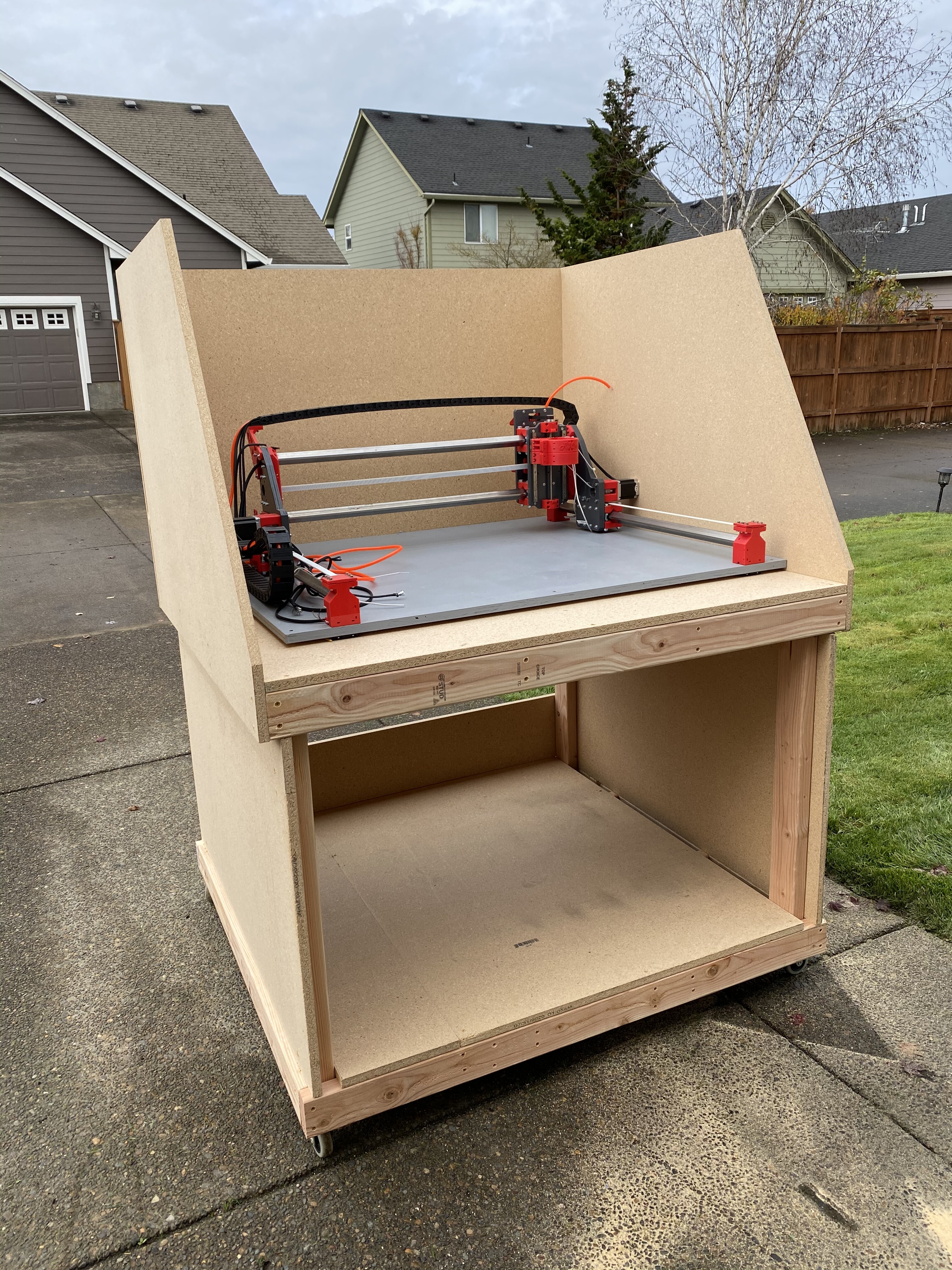
I was at first dismayed with how tall I made the table for my OX, but shortly after I started using it I changed my mind and was super glad I made it tall. Zero bending over to look at things closely. 2¢
1 Like
You might want to think about a built in lift so it can sit more solid when running.
2 Likes
I will need to find something for it to rest. Although with a few sheets of 3/4" particle board it has added quite a bit of weight to it. I see I don’t have enough particle board still. Unfortunately it’s wider than a sheet of particle board so it is taking more than normal.
I just need the top and front and should be close to having it enclosed. I’m going to cut a hole in the front and put in some plexiglass. I need to find some plexiglass still.
3 Likes
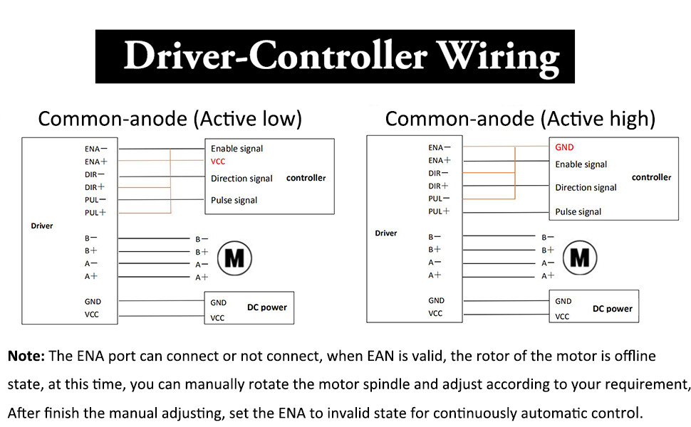
I’m assuming I should be wiring this “Active high”?
I have an alarm and power light on the TB stepper driver.
I noticed on the display I don’t have the option to move the Z Axis.
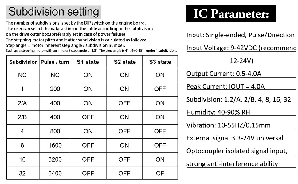
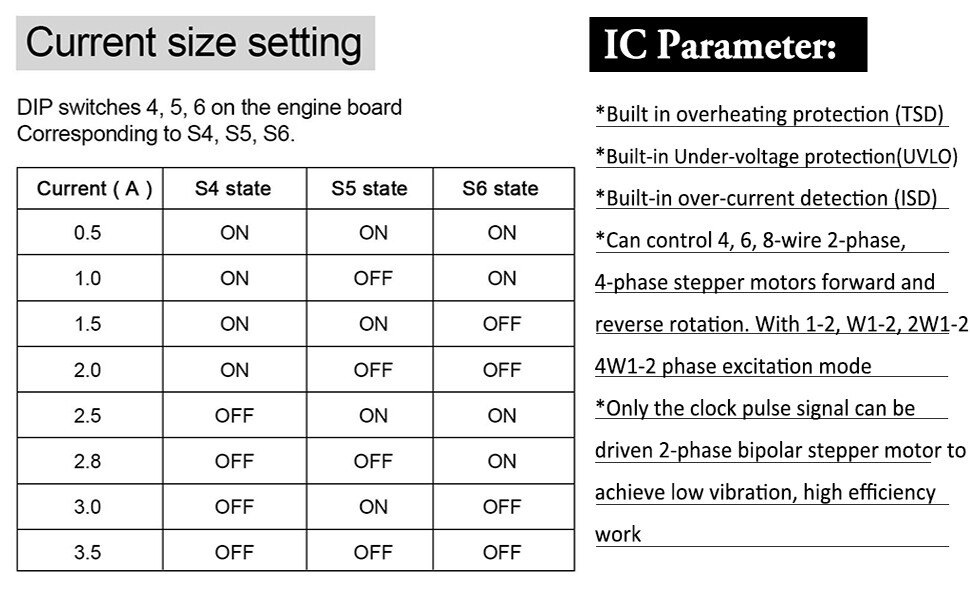
It was getting late but I don’t have any movement yet with it wired “active high” 2A. I’m also not sure about the subdivision. I have it set to 16 currently.
I’d go with “Active low” as they call it here. Obviously don’t connect VCC to the enasble signal as they have kind of drawn it.
But they call both positive supplies “VCC” which is very very wrong. Use logic level for the signal, and separate motor supply for the motor. The two should be independent. You don’t want to put 24V or so into logic ports on your board. 
16 “subdivision” microstepping is fine. Below 8 will probably sound like it is grinding itself to death. The more microsteps (the larger the “subdivision”) the lower the torque, all other things being equal. If you have problems with motor torque, you could consider going to 36V for the motors.
1 Like
Yeah, with the way they have it shown you might get confused and send 24 volts into the ground pin of your DLC board which is not advisable
Instead you want to use the enable signal on the DLC for that driver. 4wires: Step, direction, enable, gnd.
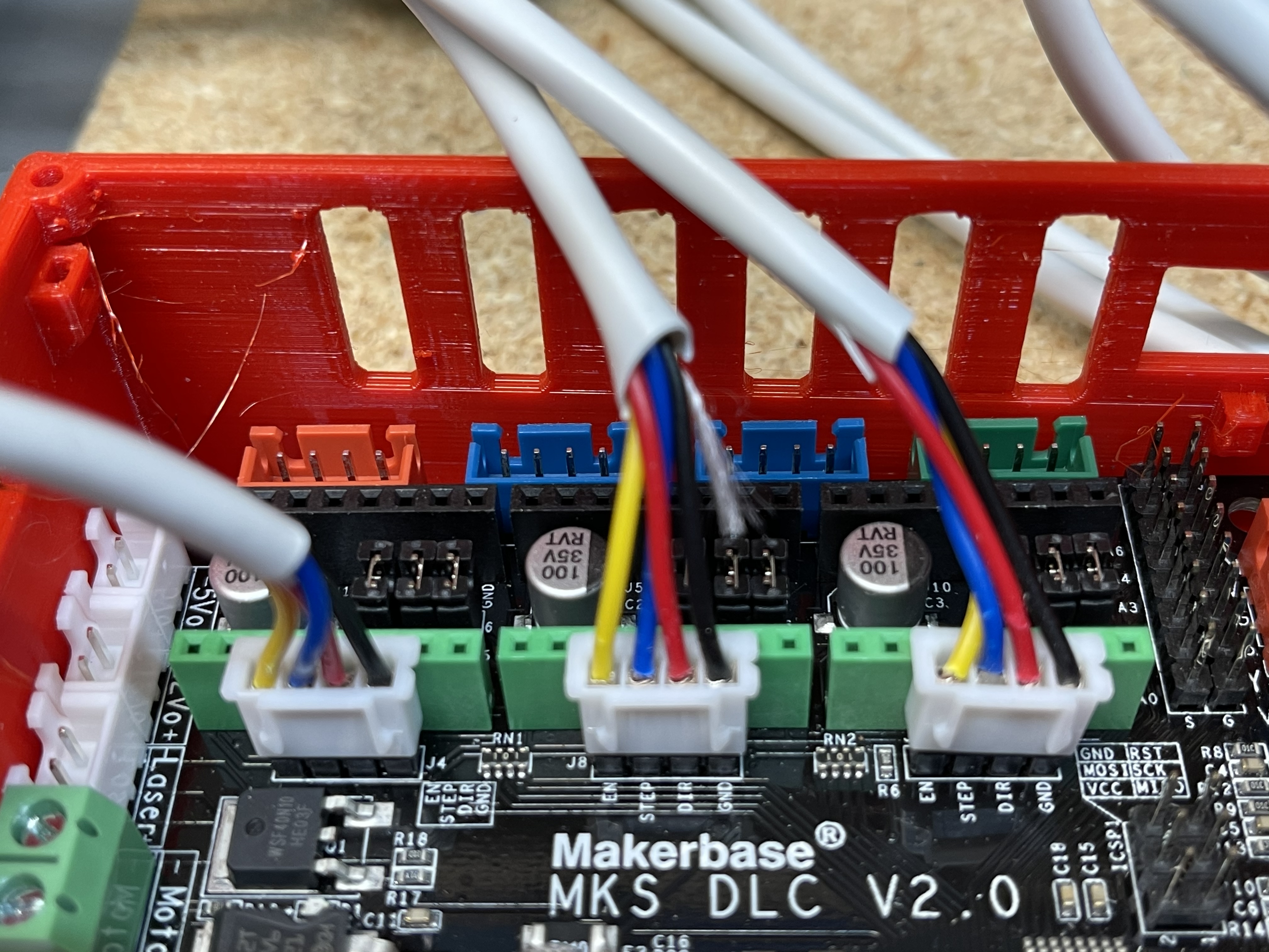
It looks like from the pictures the signal order on the board is left to right = enable, step, dir, gnd:

That’s the logic level controls from the DLC shown in a box in the upper right of that diagram external driver diagram you provided.
Then in the middle section you see the wiring from the external driver to the stepper motor obviously.
Below that you see the power in and Gnd from the power supply.
That’s why it’s broken up into three sections, it’s the wiring to the three different components that the external driver needs to connect to. Don’t cross the streams
2 Likes
Does this look right?
| TB6600 | DLC |
|---|---|
| Enable - | Enable |
| Enable + | Ground |
| Direction - | Direction |
| Direction + | Ground |
| Pulse - | Step |
| Pulse + | Ground |
Personally I think the active high layout is how I would do it. But again I haven’t used this board or driver combination before, and I am no electrical guru.
So for that:
TB6600 = DLC
Enable- = DLC Ground
Enable+ = DLC Enable
Direction- = DLC Ground
Direction+ = DLC Direction
Pulse - = DLC Ground
Pulse + = DLC Step
That is how I have it wired but I don’t have any movement for Z axis.
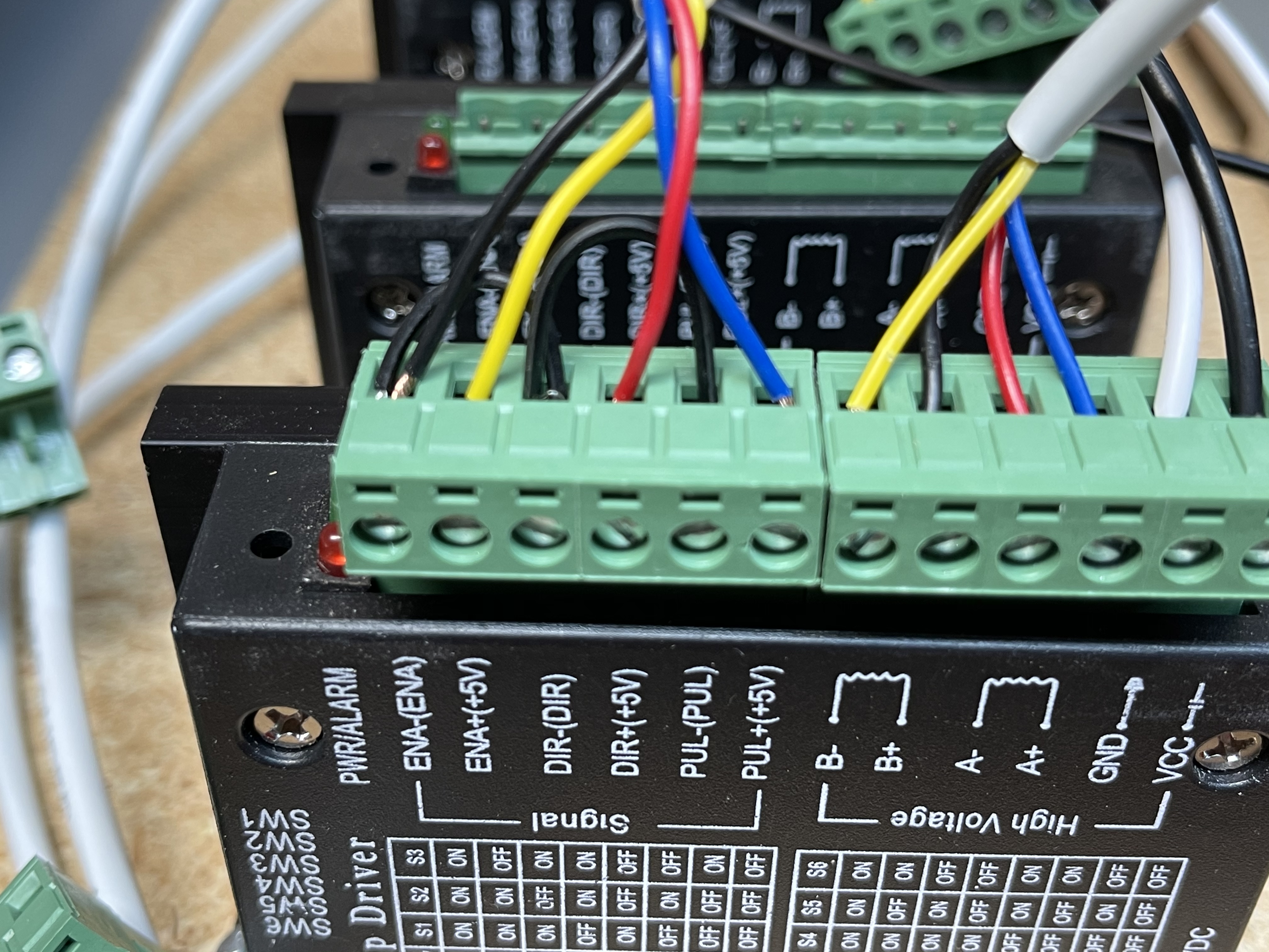
When powered on the TB6600 had the red power light and green alarm light on. Normal activity? I’ve verified the A and B motors are correct using the ohms meter.
I can connect to the DLC using OpenBuilds Control. Firmware Detected grbl version 1.1g.
![]()
Are STEP/DIR/EN pins on the MKS DLC V2.0 5V or 3.3V? (I have one, but the machine is in pieces right now so I can’t check trivially.)
My working TB6600s are hooked up to a different board which is in open drain configuration (active low). I don’t see configuration for open drain in the MKS DLC grbl source I have, though.
Looking over the Cohesion3D site using the TB6600 for a laser rotary axis on thier board, they have it setup 5+ to all the + pins, and the “-” side to the pins.
So for that setup:
TB6600 = DLC
Enable- = DLC Enable
Enable+ = 5+ from DLC Board
Direction- = DLC Direction
Direction+ = 5+ from DLC Board
Pulse - = DLC Step
Pulse + = 5+ from DLC Board
For supplying the 5V:
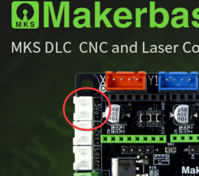
3 Likes
Thank you both! I have a moving Z axis. Yay!!
Can I loop the 5 volts through all 4 stepper drivers?
You can share the same 5V supply for all 4 stepper drivers, yes.
You are basically just driving an LED for each of the 12 lines. Each of the three lines to each of the four stepper drivers is “opto-isolated” meaning that you are driving an LED inside a package, and the high-voltage (motor) side then uses a photodiode to tell whether the LED is lit. The LED is turned on by connecting the port to GND, and the current is limited by the resistor of the opto-isolator to a level that doesn’t hurt the chip. So all that 5V power supply is doing is lighting up as many as 12 LEDs at once.
Basically, this is a really fancy arduino “blinky” sketch with 12 LEDs that are hidden from view! 
Note that this is “open drain” configuration. That’s why the config files on the cohesion3d page @Eclsnowman links to shows the o modifier for all the ports; that’s how you tell smoothieware to use open drain configuration. It also has to invert them; that’s the ! in the configuration. It’s why I was looking to see whether grbl for the MKS DLC V2.0 had an open drain configuration option, and didn’t see it.
But if it’s working, yay!
1 Like
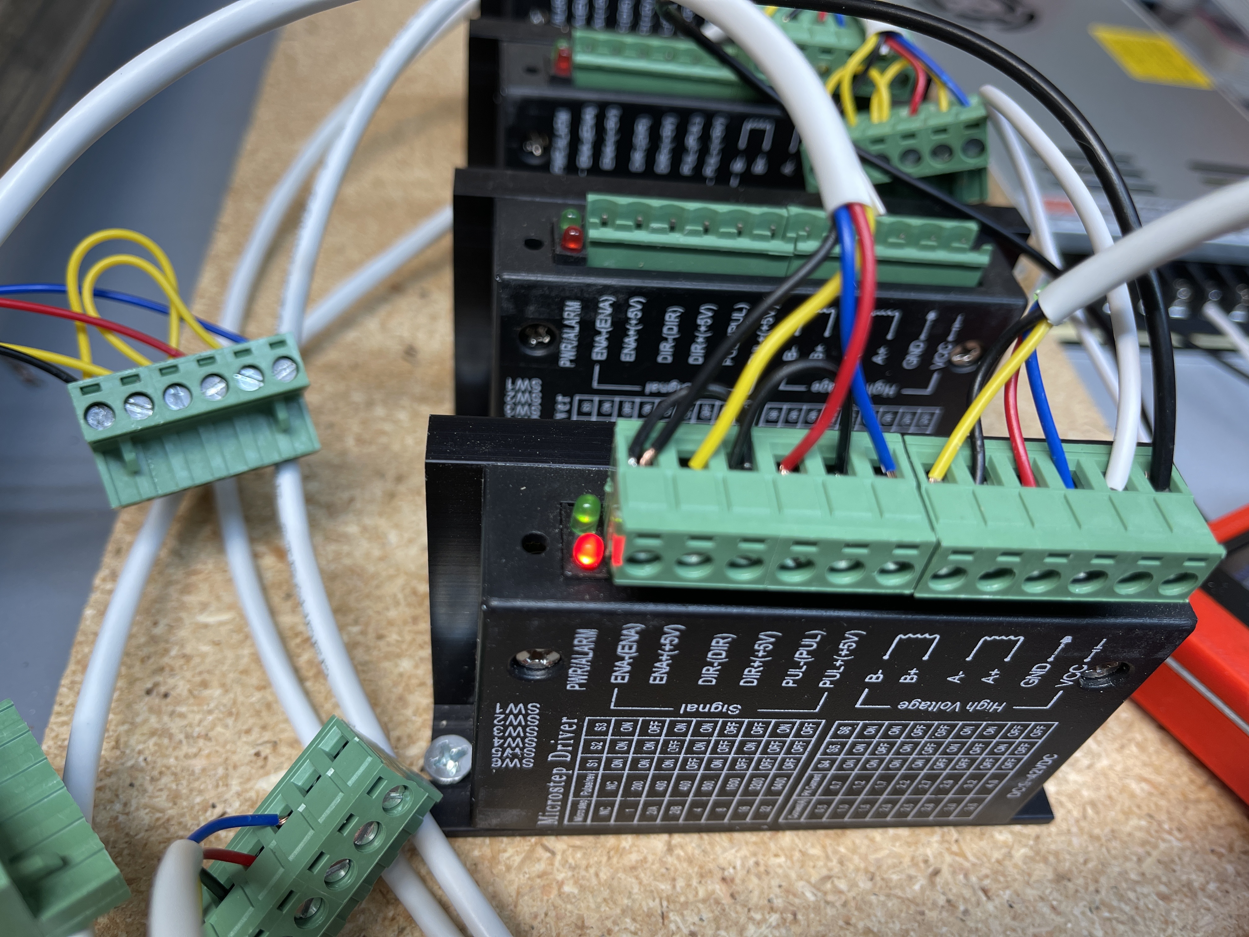
I have all the steppers wired now!! My X and Z axis move around great. My Y axis moves about 1/2 way and stops. I’m pushing 2A to the stepper drivers. I think I need to go up to 2.5A or higher to get it to push past the rough spot. These can go up to 3A. I know your not supposed to run them any higher than needed.
Not sure if this is the correct way of doing things but my thought is to get it moving around and then running some test gcode to loosen things up?
I still need to wire up the end stops.
What are the steppers rated for? I would run them at the maximum current that doesn’t exceed their rating. You don’t really want to risk skipping steps while routing.
For traveling halfway and stopping are you sure that it’s not the machine thinks it’s reached its travel limits? Or thought it hit an endstop due to noise? When you set up the machine using that open builds configurator did you set the travel soft limits?
I don’t have a grbl controller so I don’t know if they have soft limits for travel to make sure that it doesn’t over travel. The nice thing if I remember in gerbil is you can change the config by just sending commands. Or you can probably change it in that machine configurator
you used to flash it and try that.
A $$ dump will show that configuration. $20 is whether soft limits are enabled:
I set the Y Axis steppers to 3A each. After playing around with it I got some test gcode setup to run in the video below. You can see if the video it has a squeal in the Y axis direction. Not sure if I can fix it. I think it has to do with the rod that travels across to the other Y stepper linking them together. It does this when I move it manually as well. 
We have movement, click here for video
I really like the OpenBuilds Control interface and GRBL firmware. I can set Zero anywhere I want it with OpenBuilds Control. I’m tempted to not even wire the end stops. I didn’t have them on my MPCNC and it seemed to work ok. If I can get it back to the exact same spot when I home the Axis’s I should be ok.
I’ve missed this CNC stuff so much! I can sit out in the garage where it’s 59 degrees and watch this thing move around all day.
1 Like
Looks to me like the axis acceleration values could go up substantially. And also the max velocity likely. Thats the advantage of a belt driven system.
But glad to see it is moving.
1 Like