Hi all, I’m new here and hope it’s okay to ask this.
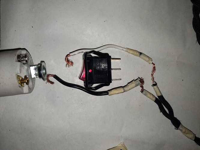
I’m trying to make a book lamp with a small red rocker switch interrupter. It has three metal tabs to attach wires to, but lamp cords only have two wires.
I tried just using the two lamp wires, putting the hot wire on the gold tab and the neutral wire on each of the silver tabs, one at a time.
(I did this partway down the cord, and attach the ends to a socket.)
First, the lamp turned on but wouldn’t turn off when I rocked the switch. The second try, the bulb blew as soon as I touched the plug to the socket.
I think I’m supposed to put a grounding wire on one of the silver tabs, but my question is, what in the world do I attach the grounding wire to? A piece of rubber? I need to be able to tuck it into the books I’m making the lamp out of.
Typically the rocker switch connects the middle tab to one of the outside tabs, alternately. It probably says “SPDT” somewhere on it. Normally you would connect the white line to neutral and connect that directly to the silver terminal on the socket, and for the black (hot) wire would connect the wall to the center terminal and one of the outside terminals to the brass screw on the socket. It’s important that you not get that backward, and it looks like you are using unmarked cloth wire. That often has unpolarized plugs on the other end, which would make this very dangerous. You can electrocute yourself by getting that backwards. 
Also, you will need to use the proper connectors. You need crimp connectors, which require a crimping tool, to attach the wires to the terminals. Otherwise you have a fire hazard.
Do you have a multimeter?
Thank you for the fast response! I don’t have crimp connectors or a multimeter. I will get the crimp connectors. Is a crimping tool absolutely necessary or would I be able to finagle without it? I did strip down the wires a lot and and planning to wrap all the little parts in electrical tape once I get them in the right place. So you’re saying the black wire should go around the middle terminator and then the gold outer terminator, and then the gold screw from the socket? I didn’t realize the same wire could go around two of them!
I recommend a crimping tool, because a loose connection is a fire hazard. Electrical tape isn’t ever a connector, it’s an insulator.
First, the black wire must be connected to “hot.” That’s the narrow of the two plug prongs that goes into the wall. The white wire must be connected to neutral. that’s the wide of the two prongs that go into the wall. If both prongs on the plug are the same, stop right there, this cord is dangerous to use for what you are trying to use it for.
You basically never strip a wire in the middle, only at the ends. So thank you for taking the picture you did! No, you won’t wrap wires around more than one terminal.
You need three wires to do this task. Two that go to the wall, and a short black wire between the switch and the socket.
The hot wire, which by electrical code must not be white and is normally black, and which is connected to the narrow prong that goes into the wall, connects only to the center pin of the switch.
One of the outer pins of the switch connects with a separate piece of black wire to the gold screw.
The neutral wire, which by electrical code is white, and which is connected to the wide prong that goes into the wall, connects only to the silver screw on the socket.
The remaining connector on the switch must be insulated. You can push an unused insulated crimp connector onto it as one way of doing that.
This is wiring that carries a potentially lethal voltage. There are books on basic wiring available at most home improvement stores and I hope also at the library. You’ll really want to make sure you understand the basics before hooking this into the wall.
I asked about the multimeter because:
- You might need to use it if you have two black wires between the plug and your switch, and you can check which plug prong goes to which wire.
- You can use it to tell how the switch works by testing which two connectors on the switch are electrically connected in each switch position.
I know it seems like a simple project until you learn that you need insulated crimping female spade connectors, a crimping tool, knowledge of how switches work, basic knowledge of electrical theory, and basic knowledge of electrical code. The rules for how things should be connected seem arbitrary some times, but basically every rule in electrical code was “written in blood” — it is there because not having it killed someone, usually more than one. It’s absolutely possible to learn to do this safely! It’s just not as trivial to learn how as it looks at first glance. “It’s just a few wires, what could be hard about this?” 
I say this as someone who has made mistakes wiring power. Including yesterday. 
You can crimp without a crimping tool but it’s been my experience that they always come loose.
These things:
look like they’re crimp tools. They’re actually smash tools.
For just a little more, these:
are crimp tools that will do a repeatable, predictable, good job of crimping terminals, and if you’re starting to build electrical stuff, it’s worth having a pair. Crimp connections, when done well, are good solid long-term connections, and you can use them in lots of places.
This type of switch:
https://www.antiquelampsupply.com/white-inline-on-off-rocker-lamp-cord-switches-choice-to-fit-spt-1-or-spt-2-lamp-cord.html
handles all the connections for you, and keeps them inside the switch body. I don’t actually like these, because I don’t think they’re as reliable as crimped insulated connectors. However, they have good ergonomics and are very clear in how they’re used/installed.
Most hardware stores carry lamp switches.
Yes, I do have switches. But I wanted to use this particular one because of the look and size.
Thanks, John. I do have some of those. I wanted to use the little red switch interrupter instead because of the look and size. I’ll look for crimped connectors. ANd actually, I have a cord-stripping tool that looks like it actually has a crimping tool built into it! It has a bunch of little parts I did not understand before and I think that is one - I will try it!
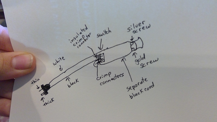
Thank you so much for taking the time to type this all out!! I think it is clear now - I didn’t realize I would use a separate piece of black wire to go to the socket. I went through a lot of videos on basic wiring but couldn’t translate it to this project - I’ll definitely watch some more before plugging this in. I’ve drawn out a diagram that I think matches your description - would you please let me know if it’s correct? Sorry for being a pain!
Yes, that looks correct! 
And I used the integrated squishing crimpers on wire strippers for years before I broke down and bought ratcheting crimpers as @John_Bump suggests. I wouldn’t go back now that I have the ratcheting crimpers, but what you have absolutely can work! You just want to make sure the wires are solidly connected; if they are loose that’s where you end up with fire and/or electrocution hazard.
Thanks so much! Planning to try to solder the wire to the interior/metal part of the connector before crimping to hopefully make sure of solid connection.
That’s what I thought for years. I learned relatively recently that’s actually not a good idea; a simple crimp is better. The solder gets into the wire and makes it more brittle. It was not intuitive for me to stop soldering connections like this.
(I say that, and today I had to solder wire directly to a switch, but the switch had only solder terminals, no screw or crimp terminals, and I made sure there was enough strain relief to avoid damage.)
I agree that soldering makes the wire brittle. I’ve run into this many times in cars, where I soldered a broken wire only to have it fail again a year later because of vibration.
With that said, on stuff in houses, I think soldering is an okay idea because there isn’t the relentless vibration, and then you have a connection that doesn’t pull out if it’s not crimped quite tightly enough.
I’m still arguing this one with myself. On my car I just crimp things. In the house and on appliances particularly I usually crimp and solder, because I think it’s reasonable to expect that at some point an appliance cord is going to be pulled on, and that’s when a lousy crimp will come apart and expose a live wire, where a crimped and soldered connection will hold together.
Side discussion on wiring a switch.
What Michael said is completely right: wire the hot line to the middle contact of a switch, and then wire the switched line from one or the other terminal to the load.
In this specific case, I’d be tempted to plug the hot line into one of the outer terminals, and run the switched line from the center terminal to the lamp.
The reason I’m thinking about this is when the switch is open, neither other terminal has voltage on it, and when the switch is closed, only the center terminal is live. In no case is the other, unconnected, terminal live. That seems like a worthwhile increase in safety.
Well, actually what I’d do is cut off the other terminal and put a blop of epoxy over it so it would never be a problem, but: opinions on reverse wiring a switch for safety?
That’s a really good idea. Using the center is convention, no electrical reason I know of!
Thanks to you both for all of this knowledge. Hot/black into one outer terminal, connect socket to center terminal with black wire, insulated connector onto third terminal. Neutral wire bypasses the switch, directly to the socket.
I just realized we never got to this question, and I didn’t see a third wire in the picture. If you don’t have a third prong going into the wall, you don’t have a connection to ground at all. It is common for lamps to have only hot and neutral, and not to have a ground wire at all.
I finally noticed you said you are making the lamp out of books. I hope it’s an LED lamp so it won’t get hot enough to burn the books! No “Fahrenheit 451” here! ![]()
Besides asking any new questions that come up, feel free to post pictures as you go along, and pictures of the completed project. 
Yeah, I’d like to see a picture of the project when it’s working.
It’s inspirational to see what other people make.

