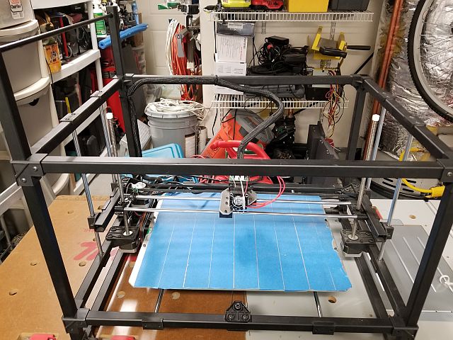
The work area is 12 inches x 16 inches x 10 inches. It is made to be modular and the height can be increased. There was a 14 inch Z axis kit but I do not know if it is still available.
I have not tried to turn it on so I do not know what does or does not work.
There is are lot of fixes that need to be done from the original design to make it work more efficiently and safely.
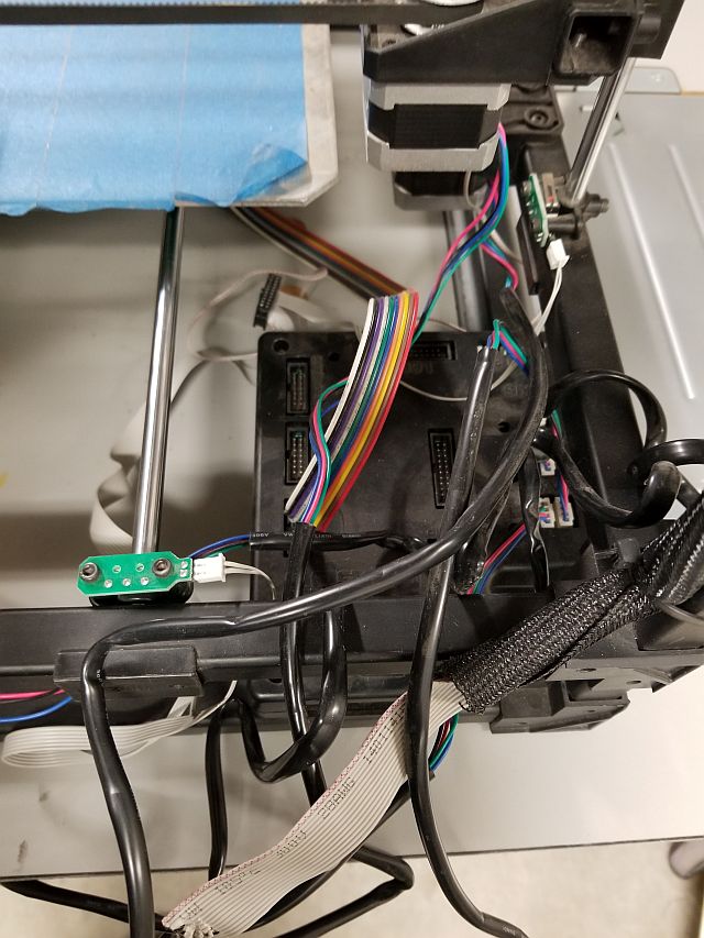
I would not trust the ribbon cable. You’re right at it’s average maximum current capacity of around 2 amps depending on gauge. Also the run is around 30 inches so there is some resistance loss there too.
Typical heater cartridge 40W/24V=1.66A that wouldn’t be a 1.5x safety factor. I thought most ribbon cable for hot end heater cartridges used multiple runs though? Anyway I admit I’ve never wanted to use ribbon cable for heaters.
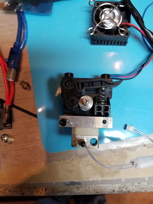
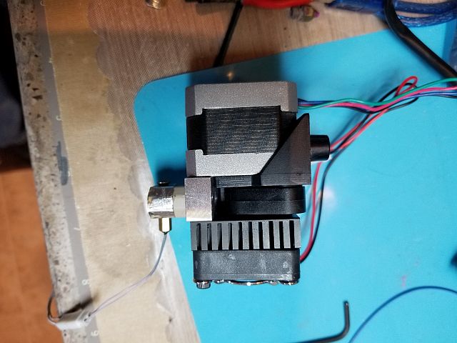
So today I took the hotend apart. It is very compact. I am not really sure how well it really works but for right now I do not feel like making any adaptors just yet. The stepper is 0.9 degrees as are the rest of the stepper motors. I know there were complaints on the stepper performance but I am willing to see what the fuss is really about before I start replacing them and having to make brackets and replace pulleys.
I found a MKS Gen 1.4 controller board in my parts bin so I am going to use that to make everything go. Once I have it running smoothly, I will see about a nice 32bit board. I had to order new 24V heaters because all the ones I have are 12V. I also had to order some 24V 40 mm fans.
Today I finally worked out the bugs on the newest Marlin release and successfully flashed the MKS GEN 1.4 controller board. I have the Full Graphics Smart Controller which I had to turn the ribbon cables 180 degrees to work with the MKS board. I have separate drivers for each of the Z axis steppers. The 24V heaters came as well as 16 ga silicone wire for the heater bed mod. I need to see where the best place to mount the board will be for maximum cable reach. I am also going to replace the stock 2 wire non-led limit switches with 3 wire LED versions.
The ribbon cables are paralleled. 3-wires to the hotend heater and 4 wires for the heated bed. They aren’t overstressed. However the bed connector can work loose from the constant motion, corrected by a locking connector in later versions of the Rigidbot.
@edwilliams16 Thanks confirming that the ribbon cables could handle the load.
Since I’m using a different controller board rewiring everything is not that big of a pain. I am just not a big fan of using multiple wires to handle what a single wire can.
There’s actually good reason to use multiple wires in parallel for carrying lots of current; it has more surface area for cooling than the same amount of metal in a single wire. I do this on purpose on my electric tractor, for instance, though that’s carrying a lot more current (up to 200A at 48V )
Not saying for a moment that you shouldn’t do it your way, just that there’s a valid engineering reason to have done it.
The stock hotend works very well for PLA and ABS. You are limited by its design to printing temperatures lower than 245C. After moderate use at the higher end of this range I found the PTFE tube starts to break down. Also, the PEEK heat brake between the cooling block and the heating block will start to deform if you print at any higher temperature. If you have not had a chance yet, you will find reliabuild3d.com to be a very critical resource. They sell replacement parts and upgrades for these original rigidbots. The stock extruder doesn’t constrain the filament well enough to print flexibles like TPU, but they sell a replacement cooling block that makes printing flexibles very simple. You can also get replacement PTFE tubes, and an upgraded heater block. There is an upgrade to replace your ribbon cable on your heated bed, like has already been done with your extruder cable. They also have the original firmware and other such resources. Maybe you know about this already.
@swoolstenh Thank you for all of the information. One of the reservations I have had is using the existing hotend. One of the first things I wanted to try was TPU. I have a friend who needs a flexible piece printed. I actually purchased a cheap direct drive to add to my older printer but never did modify it. I was thinking of mounting it to the RBB but was going to go with the stock first and see what kind of results I would have.
I was not sure reliabuild3d was still supporting the RBB but I will contact them and see what they have to upgrade the existing hotend.
I am going to upgrade the cabling to the heater bed. Not a big fan of the ribbon cable.
I have already loaded up a MKS GEN V1.4 board with the RBB profile. I am just trying to get the current set correctly on the drivers so I do not burn out the stock steppers. I have other steppers if I do.
The holidays have gotten in the way so I will hopefully have it actually doing something in the coming weeks. Thanks for stopping by and your comments!
I’d like to back up what @swoolstenh said; I’ve got a similar direct-drive head on my RF100, it’s reliable and really good at flexible material, but also uses a short PTFE section in the heatbreak.
When I experimented with PETG on this machine it wouldn’t flow until I put 250c on the hotend, which promptly burned and warped the PTFE. The printed job looked ugly and I had to rebuild the hotend afterwards, getting the burned ptfe out of the heatbreak was… interesting.
You should be able to get an all-metal heatbreak if it’s a common design; This post reminded me that I’d been intending to do this and so I now have some of these on the way.
My hotend uses MK8 components, but this is quite a loose ‘standard’, measure up carefully since ymmv.
Direct drive heads are the only way to go with flexible materials, my other printer has a bowden system and is pathetic with any sort of flexible or semi-flexible material. I know, I’ve tried…
Also; remember that work-hardening cables by flexing them will increase resistance in the wires too (not by much, but it happens); another reason to be generous in sizing the heater wires…
I have used the all-metal XCR3D BP6 hot ends several times now. They use set screws for holding the heat break in place and I replace the set screws with socket cap screws that stick past the heat sink for easier hot end servicing.
I just put an Orbiter in my latest printer and it’s small and light. Version 2 was just released, but 1.5 is what I have and it seems good.
So after doing some homework and looking at my time and materials, I purchased the upgrade parts from Reliabuild3D. All in with shipping was $60 which was the cheapest option. It will all be plug and play which is what I was looking to do for a quick startup and troubleshooting. It is difficult to try and troubleshoot print issues if you do not have a starting point. There are definitely a lot of improvements to be made but I want to address them one step at a time. I should have the parts in a few days.
I need to start looking at modifying the heater bed next. I noticed some oxidation between the PCB and the aluminum plate but did not see any breech of the PCB screen and traces. Any good ideas on a material that would hold up to the heat and not act as an insulator that I could put between the PCB and aluminum?
I made a lot of progress so far this weekend. My upgraded hotend parts came and I modified the heatbed from ribbon cable to 14 ga silicone wire. I had to go the nuclear option on the heatbed due to a short in the ribbon cable pin connections trying to use them. Most likely self inflicted! I had to solder the wires directly to the bed. This is actually one of the mods that previous owners have done due to the melting of the ribbon connector. Mine was ok but did not want to risk a meltdown.
My saving grace is that I have an old (50 odd year old!) Weller 8200 soldering gun. 100 watt / 140 watt.
Soldered to the headbed without issues.
It will be a few weeks until I can get it back together due to some travel.
It has been awhile since I have updated the build but I have accomplished a lot.
I rebuilt the original extruder with the updated parts from Reliabuild3D. The only issue I see is that the PTF tube is a little long so I will have to shave the nozzle down about a 1/32 for a flush fit on the hot end. Since I am keeping the 24VDC operations, the board did not have a 24 VDC output for the hotend fan. There was an additional spot for a 24VDC connection that is always on so I used that. I could have modified Marlin to use E1 but did not want to mess with it. I did a PID tune on it and it stays rock steady with only a +1 C fluctuation now and then. I will see about modifying the printer with another hot end at a later date.
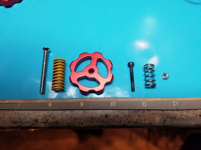
The bed heater works great now that I used 3M 468MP to adhere it to the print bed and insulated it with a sheet of cork. I used 16 GA silicone wire to connect the bed to the controller. I also modified the way the bed connects to the Y axis for leveling. For some odd reason, it did not have knobs to level the bed and both ends were threaded so it was not really user friendly. you can see below what I used in place of the stock parts. The only trade off is that I lost about a 1/4 inch of Y travel at the front of the printer where the adjustment knob hits the frame. I can always get or print smaller adjustment knobs. I had a piece of glass that was the correct size for the bed.
I did not need to PID tune the bed. It stayed rock steady without tuning.
I had to modify Marlin due to all the axis being reversed even though I used the RBB defaults. I replaced all the limit switches with ones that have LEDs to show when they are activated. The controller board and display are just in a temporary location. I added drag chain to the bed and Z axis.
I will be doing some printing and tuning this weekend finally. Will take some pics and post.