Current wire diagram (with location for future interlocks)
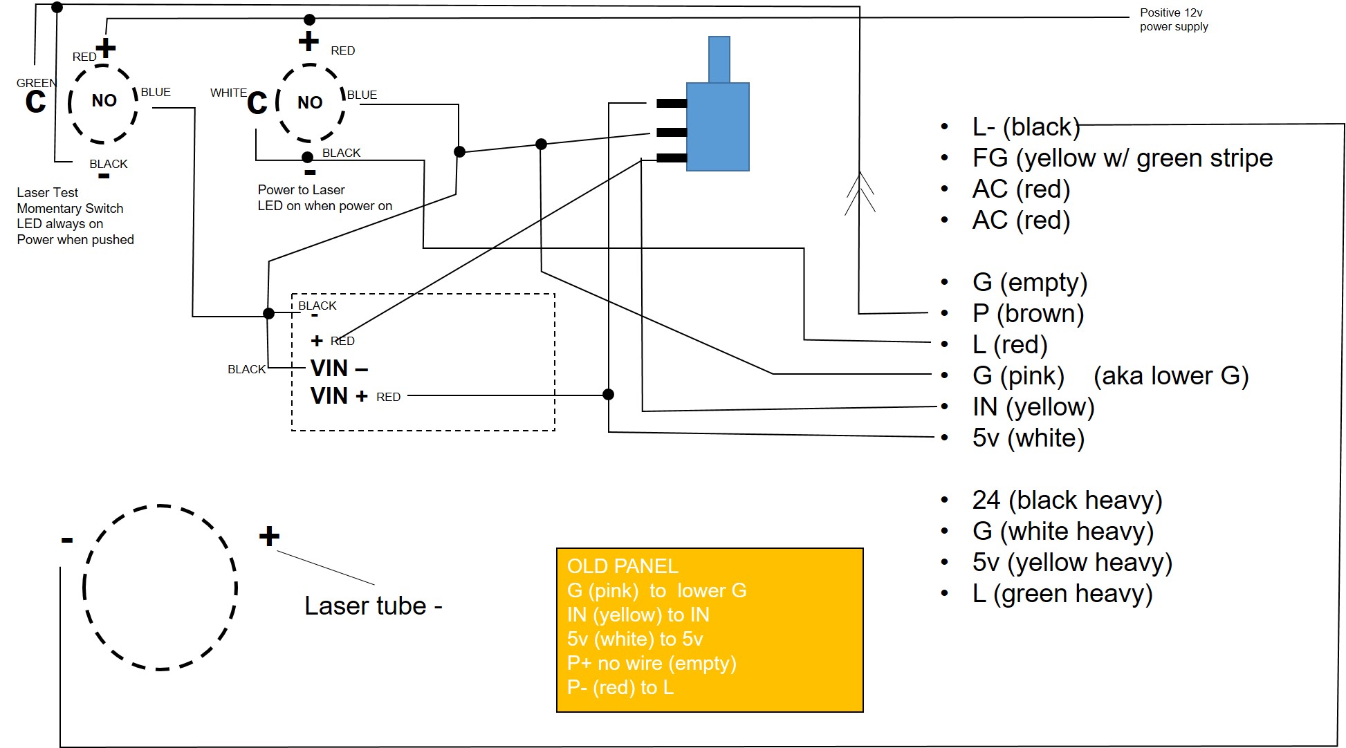
Some clarification is needed:
Since all the wires that were connected to P were removed, I assume that means that the Black and Green wires coming from the Enable Switch are not connected to anything
in #7 you say that:
… how can the Enable LED come on if the BLK (LED-) is not connected to anything??
Going forward we may have to use your DVM to troubleshoot this problem.
Take a look at this (or similar) video https://www.youtube.com/watch?v=TdUK6RPdIrA&t=26s
Post a picture of the front of your DVM so that I can help you with the settings if we need to use it.
Sir, please check out this quick video. Hopefully this will be a little bit clearer.

Also, as referenced in the video, I have this Multimeter coming on Wednesday to replace my 30 year old POS meter.
The video does not play?
You’ll have to click on the youtube link in the upper left hand corner. It’ll open in youtube and play.
I changed the settings. Maybe this will work now…
Thanks for the video and sorry it took me a day to get back.
I am replacing my roof so its kinda crazy here.
Am I losing it?
Is the switch that you show in the video actually the Laser Fire (left side of the panel) that you are saying was connected to the P? (GRN-BLK-BRN connection)
The Laser ON switch (alt action) should be connected to P?
In the video the labeling is Laser Fire is on the left and the Laser ON is on the right correct?
Are these switches reversed?
According to the amazon drawing, the only white wire is on the push button (which should be the Laser Fire) and in the video that is on the right???
The wire colors do not seem to match what the amazon spec says for these switches? I do not see a yellow wire anywhere which should be on the Switch ???
My concept of searching problems is “reduce to the minimum”.
So I would first disconnect the cables for the button lights and only connect the switches.
The laser enable switch should connect G and P when active. The laser test button should connect G and L when pushed. If that works, go figgure out the button lights.
I also think we may need to verify that the information we have on the switch and PB connections is correct.
I agree with @cprezzi…
After we resolve my questions above regarding switch positions:
Disconnect both LEDs and only wire the switch/pb to the LPS as the previous schematic shows.
- That means on the Laser On sw disconnect the Red and Blk wire
- On the Laser Fire disconnect the Red and Black wire.
Ok.
I unplugged the LEDs (red and black wires).
There was a yellow wire on the test fire switch (left one from the video) but I cut it off as it didn’t connect anywhere that I could see in any of our drawings.
There was also a brown wire on the Enable switch (right one from the video) that i removed as well.
I plugged the Green wire from the test fire switch into the L on the LPS, and I plugged the White wire from the Enable switch into the P on the LPS and tried, and it did exactly the same thing as before. When pushing the test fire switch, the laser fired regardless if the Enable switch was on or off. When pressing the Enable switch it would continuously fire the laser.
So, if Green was in L and White was in P, or if Green was in P and White was in L, it had the same effect.
I’m so lost. Maybe I should stick to my day job. Ha!
So should the Enable switch be going white to P and Blue to G? Then the Test switch remain the same with green going to L?
Exactly. From your video I can see that the left button is connected to P, whch is enable, not test fire! If this is the momentary button for test fire, you need to connect it to L and the right button (on/off) should go to P.
1 Like
You have the two switches reversed…
Does this make sense???
I switched the wires so that the Left button (test fire) is connected to L, and the right button (enable) is connected to P, and the same thing happens. When I engage the Enable button (right) it fires the laser consistently until I disengage the switch. When I press the test fire (left) switch, regardless of whether or not the enable switch is engaged, it will fire the laser.
When I run lightburn and execute a cut, it will still run with the Enable switch in the off position.
Take a look at this post I am starting to think this is your problem.
To prove it we have to make some measurements did you get your meter?
Good morning. From Utah huh? I grew up in Salt Lake. My whole family lives there. I’m not there now. Great state!
So, what I gathered from that other post is I may have a bad diode. All the rest of the stuff was alien to me. So this will be interesting.
I did get the meter. When you say “ground P and measure L” does that mean you stick the black end of the meter on P and the red end on L? vice versa when “ground L and measure P”
Let’s try it the easy way first.
Set your meter up this way:
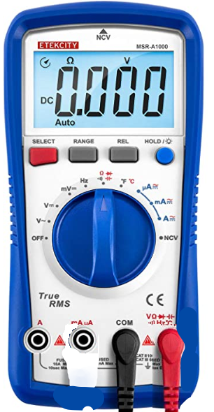
Note the placement of the black and red leads.
Meter check
Connect:
Red lead to the Black lead
- What does the display read & post a picture of the meter taken while measuring
-It should read 0 ohms meaning the meter is set up correctly.
EDIT: you need to ensure the display shows an ohms symbol at the top.
you may have to use the “select” or another button to get to that mode.
Diode Check
With the power off and the machine unplugged:
All connectors unplugged from LPS.
Connect:
Red lead to P
Black lead to L
2. What does the display read & post a picture of the meter taken while measuring
-Should read High resistance*
Connect:
Red lead to L
Black lead to P
3. What does the display read & post a picture of the meter taken while measuring
-Should read High Resistance*
- not sure what that the meter displays for an open circuit.
Hello. Sorry it took me a couple days to get back. Had some other issues come up that took precedence.
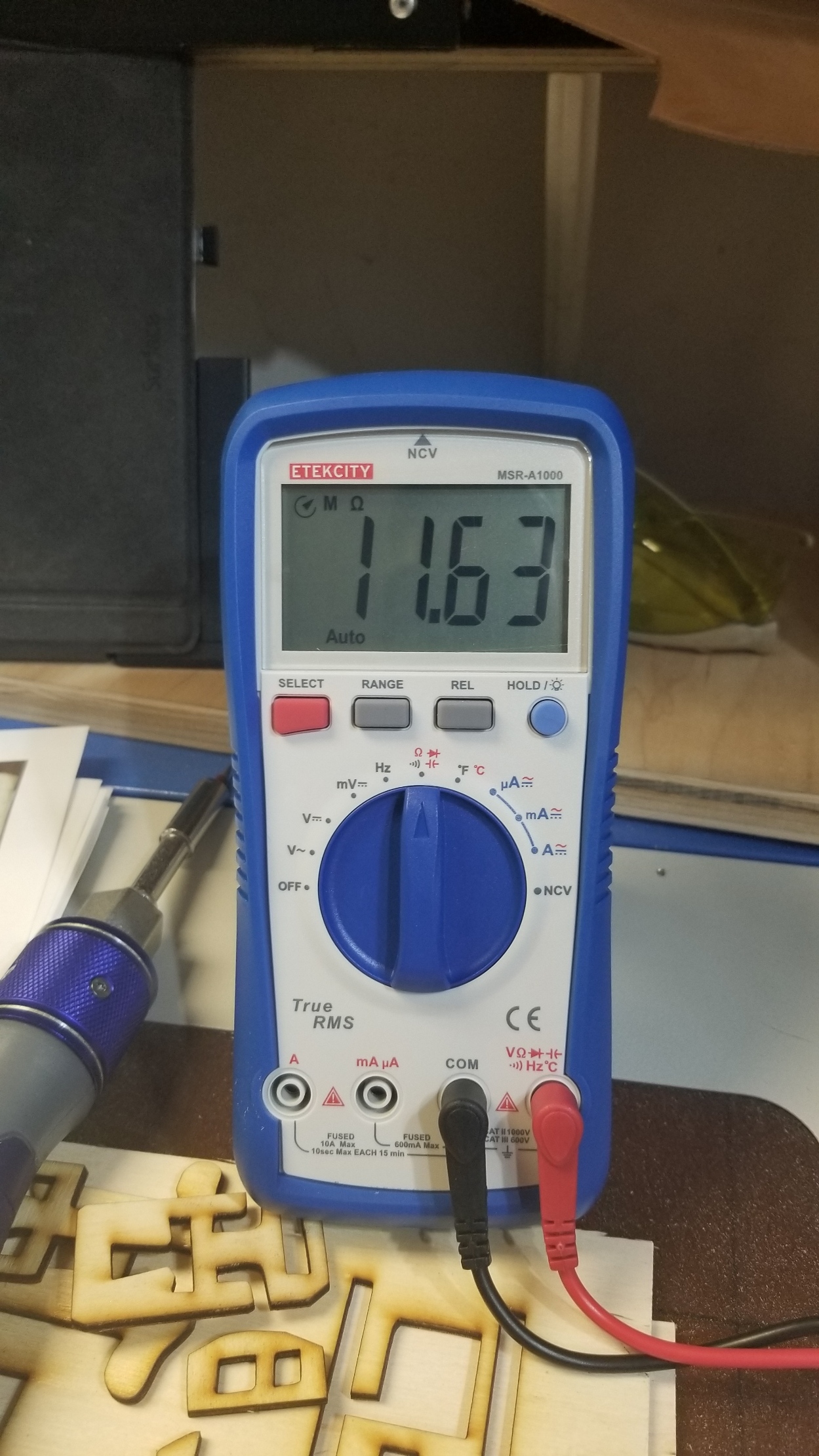
- This is a picture of when I touched the two leads together. They had random readings when I initially touched them together, but eventually they zeroed out (after about three seconds).
I then unplugged everything from the LPS.
- Initially, when I touched the Red to the P and the Black to the L, this is what I got.
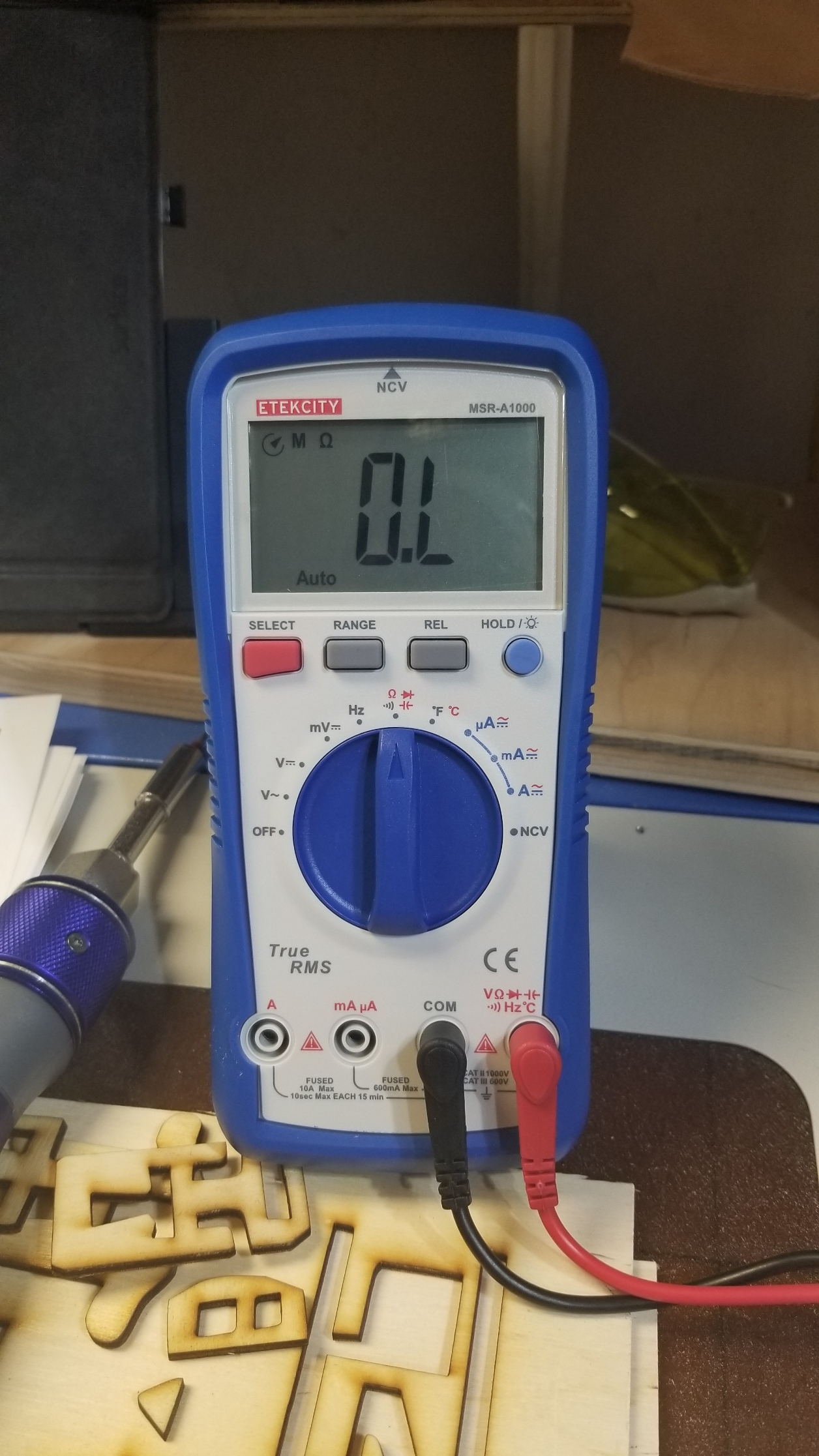
- Then when I connected the Red to the L and the Black to the P, it didn’t read anything. It just displayed 0.L
Then when I went back to Red lead to P and Black lead to L, it displayed 0.L.
Something is not right.
- when you short the meter leads it should read 0.0 not O.L which means it does not see the leads touching.? We must have the meter in the wrong mode or something?
Let’s test this another way.
We are going to read the change in voltage on the open P pin when we ground the L pin with the supply energized.
The laser may fire so wear your eye protection and close the back laser cover and the cover over the main compartment.
- Leave the black and red leads plugged into the meter like they are.
- Plug in only the AC power plug to the laser power supply. (Leftmost 4 pin connector)
- Set the meter to DC volts. (I think that is two positions clockwise from the OFF position on the meters rotary switch.)
- Connect the meter red lead to the P pin and the black lead to the gnd pin. Ideally connecting this with alligator clips or something. Don’t short anything out.
- Take a picture of these LPS & meter setup
- Turn on the machine’s power.
- Take picture of the meters reading, it should be reading P at about 4.7v.
- With the meter still connected like above.
- Now connect the L pin to the ground pin.
- The laser will probably fire, did it?
- What did the meter read while the L pin is grounded?
- It should read 4.7V if good or about 2V if it is bad.
Sir, I’m sorry I haven’t gotten back to you yet. I haven’t forgotten, just haven’t had the chance to run these tests. I got activated to assist with the LA Riots. I will hopefully be able to run this test in the next couple of days.
Thank you for your assistance. I really appreciate it.