There is a reason for this. The digital panel is simply a PWM (DF) signal from 0-100% applied to the power control on the LPS. It has no feedback for how much light it actually puts out at a given %PWM
Every K40 system if different in terms of how much current the tube draws for a given Duty Factor control on the LPS-IN. The light output (power) is also a function of the current and the state of the tubes gas and that changes with age of the tube etc.
As the tube is used-up (a function of time and power level usage) the relationship between current and light output changes. Therefore the relationship between %DF (current) and the light it outputs decreases.
That means that you cannot count on a certain DF providing exactly the same power from system to system and from job to job on the same system.
This is why a meter is required to know actually how much current is being drawn. As the tube ages more current is needed to provide the same light output until finally the tube will not produce any output at any current. This is why it needs adjust-ability which you can get with a pot or a digital panel.
Geek pause: the tube is actually a negative resistance device whose gas under goes dissociation during ionization. So admittedly what I claim above is not totally accurate as the the tube acts electrically differently in pre-ionization vs after ionization.
[http://donsthings.blogspot.com/2017/03/laser-response-charcteristics.html]
I think the digital panel give users the feeling that it is precisely controlling power when it is really no better than the pot at its repeatability.
@NedMan 's case is interesting because the LPS and tube were fresh and more ideal than our machines are actually running at.
I think all these perspectives are essentially the same.
Yours is better in that it explains it simpler :)
During engraving I have always thought of the pot as a sort of “contrast” control.
The element that most seem to ignore is that the power out of the tube changes over time for the same setting on the pot or the digital panel.
The real issue is that a current meter is essential no mater what method is used to set the LPS max power; digital or analog if you are employing PWM control from the driving program.
I wonder why they removed the meter:
They do not understand that the laser current vs PWM changes over time?
They want folks to run their tube at high levels so it replaced more often?
Since the stock machine only dithers the power setting is less critical
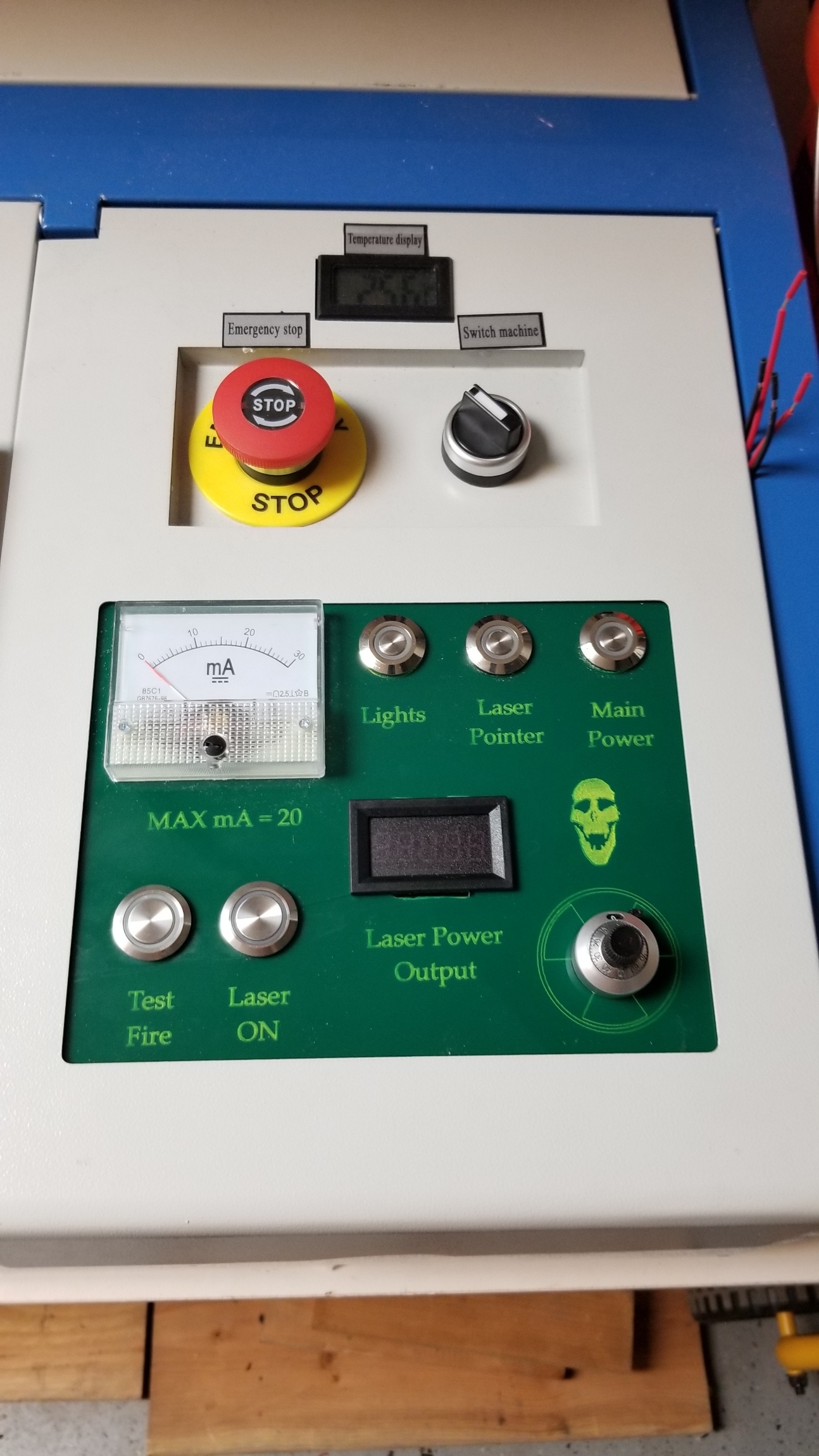
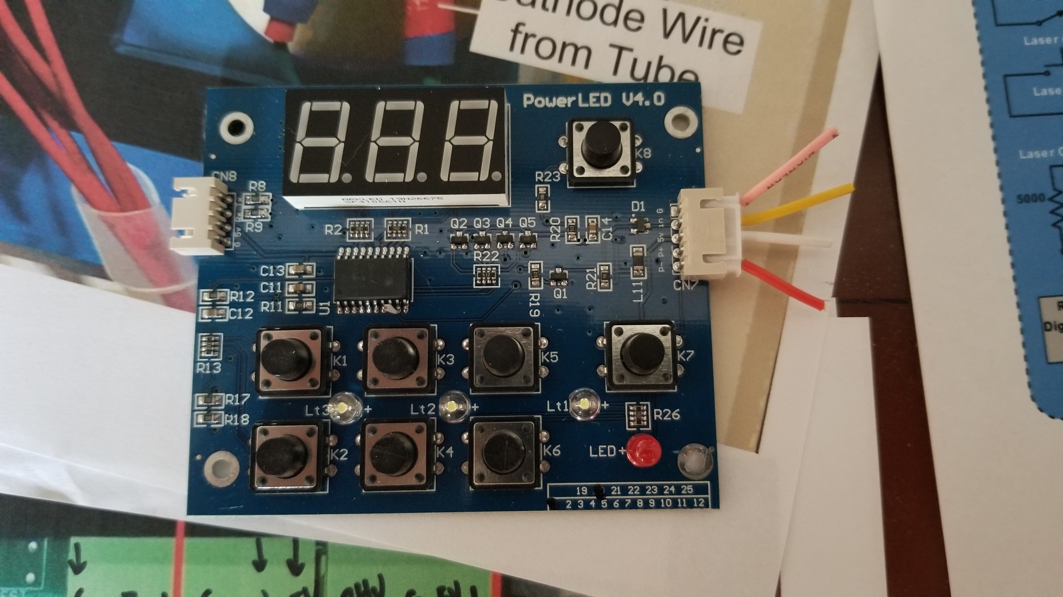
Hello. New to the Forum, new to the K40. I’ve had my laser for about a month now. Joined the forum today (22 MAY 20). I’ve made a lot of upgrades to my laser thus far, but not an Analog mA meter. I’ve put a Z Axis bed on it. Put the Cohesion 3D laserbrain in it. Have the LightBurn Camera. Replaced the shotty lid arm with a pneumatic one. But my question is thus: What wires do I use from the crappy digital meter and replace it with a Potentiometer? I know how to wire in the mA meter, and I have a precision potentiometer with a digital display, but I don’t know where to run the wires for the display and PotMeter. I am looking for suggestions?
I appreciate any help I can get.
I understand that the lightburn program adjusts the power from within the program and that the PotMeter I put in will not affect the overall power settings, but I mostly want to get rid of the POS Chinese stuff that’s on there.
A close-up picture of the solder posts on the pot with the diagram of the resistor showing.
** As the attached picture shows these pots often have the “wiper” on the bottom unlike other pots where it is located in the middle.
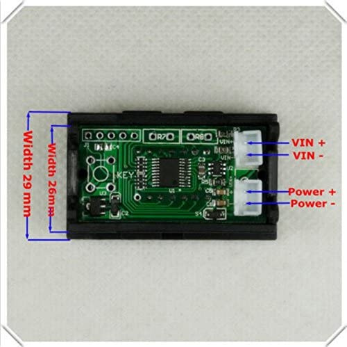
More information on the digital meter as the ebay link doesn’t define the connections.
** i.e. there are two plugs but its unclear which is power and which are measurement inputs.
** Generally there should be a pair that powers the meter and another pair that connects to the load.
** The spec on the meter is also confusing “DC 0-4.3000-33.000V”. Is that 0- 4.3V or 0-33V or what ? Perhaps it depends on how it is hooked up.
Hello Sir. This was extremely helpful as I was able to get my POT and digital display setup. Mine is exactly like yours, except blue and not red.
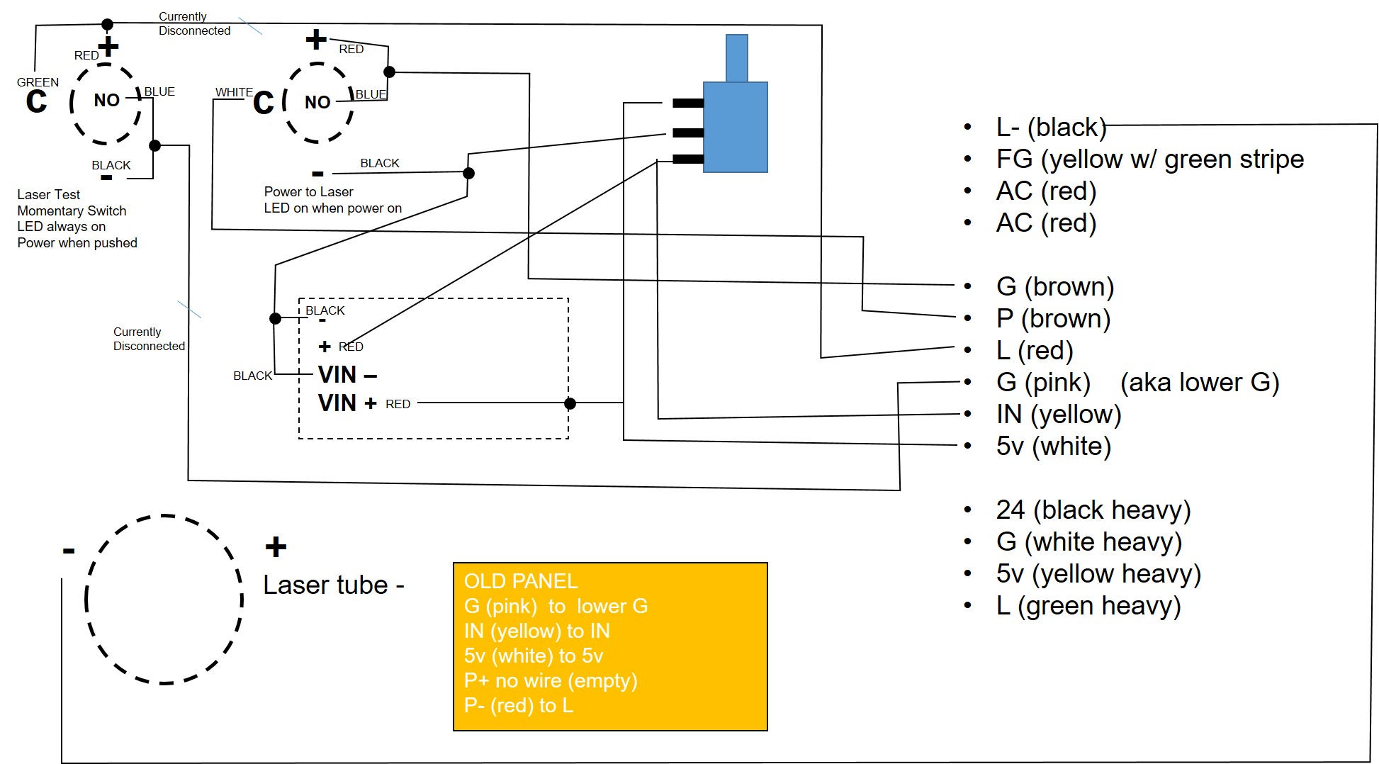
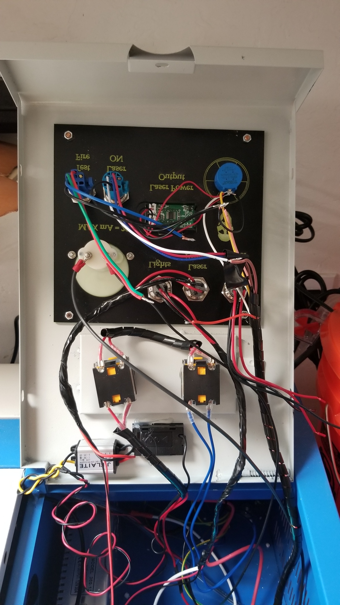
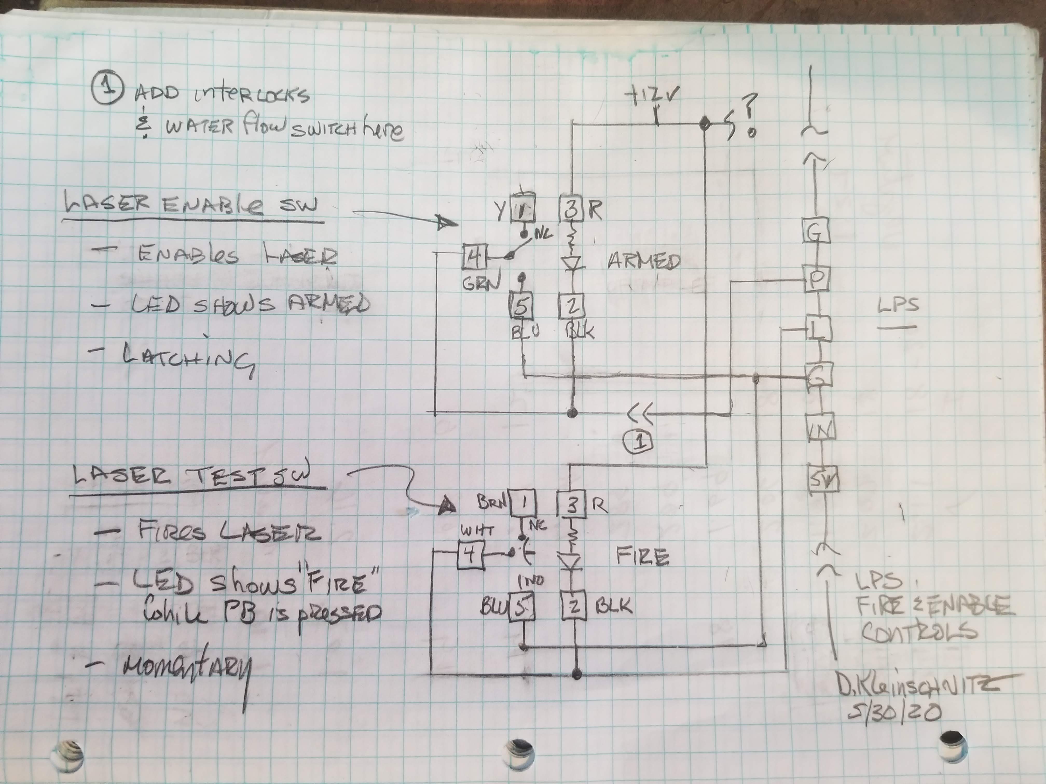
I’m now having problems with my buttons. I’m not sure the Laser Activate (power to the laser) and my test fire momentary switch are wired properly. I’ve attached a diagram of how I have everything currently.
I have disconnected my laser test switch because I don’t think it was hooked up correctly. I’m not sure my Power to laser switch is correct either.
For my test switch, I have a momentary push button. I would like to have the LED on all the time, but only power when I push it. Not sure I had it wired correctly.
For my Laser Power switch, I would like for the LED to come on, only when the power is on (button pressed and in the down position).
At some point I would like to bypass the cheap twist main power switch, but I’ll live with it as it is for now. I have the switch already in my new panel (push button Main Power) but it isn’t hooked up to anything.
Attached is a sketch interpreting what you want to accomplish.
Check my work as I did this before coffee!
NOTES:
Wireing
I used the information on amazon. Warning; interpreting these specs can be error-prone.
LED Power
The leds in these switches are 12v. I assume that means they have internal resistors.
Do you have a 12V supply available?
If so use it to power the led’s
** If not I would consider one because lots of accessories, like cabinet LED strips, use 12V.
Otherwise we can try and connect to the LPS 24V.
** We would need to measure the switches LED current at 12V to determine what resistance to add in series for a 24V connection.
If you use the 5v I suspect the LED will be too dim to be useable.
Armed LED
When the laser enable switch is latched the led in the switch will be on showing it is armed. If the laser enable switch is latched and the LED is not on then this indicates that the interlock circuit is open. I have found this useful to show me that there is a cover open or a coolant fault.
Fire LED
The fire switch will hold its LED on while the button is pushed. This may not be a useful indicator. Since your finger is already on the button the state is obvious? Then again if you push the Fire button and the LED does not light you know something is wrong.
You could wire the fire SW led across 12V and it would be on all the time.
Interlocks
I highly recommend that while you are modifying the wiring add; interlocks on the covers, a water flow sensor in the coolant and a temperature sensor. These can be added in series at point A
Thank you Sir! This really helped and got me back up and running. I had several of my wires originally going to the wrong places, and your assistance has put me right. I didn’t even think about the 12v power for the LEDs, but I have fixed that as I have a 12v stepper for the LED lights inside the cutting area, and it powers my laser pointer as well.
The only thing that I have an issue with, is the laser is “armed” all the time now and the enable switch actually fires the laser. So when I go to “enable” it, and I press the button, it fires the laser.
The test fire button works perfectly.
I do have a flow meter installed on my coolant tank so I can monitor coolant flow. I also have air assist and an upgraded exhaust fan.
You are a life saver and Thank you from the bottom of my heart for taking your time to assist me.
When you switch the Laser Enable Switch to ON does it fire the laser momentarily or does it stay on while the Laser Enable Switch is ON?
When you switch the Laser Enable Switch to ON does the led on that switch light and stay on?
When the Laser Enable Switch is ON does the Laser Test Button fire the laser as long as you push the button?
When the laser Enable Switch if OFF does the Laser Test button fire the laser?
Do you own and are able to use a DVM?
So we can stay in sync, Please answer the above questions numbering each answer with the same number as the question
----------------- Editorial ---------------------
I am disappointed that you do not have interlocks. They are necessary to keep you safe! Your eyes are not repairable from a simple reflection mishap. Laser glasses are not the solution and interlocks switches are a few $ and some wire!
A flow meter is NOT sufficient to protect your tube & machine you need a flow and temp sensor that will automatically shut down your laser power due to a fault. If not you most likely will be back here asking about where to buy a new laser & power supply which will cost more than you paid for the machine.
Just saying…
When I press the Laser Enable Switch to on, it fires the laser and it stays on while the Laser Enable Switch is ON.
When I switch the Laser Enable Switch to ON the led lights and stays on.
It doesn’t matter if the Laser Enable Switch is on or off, I can still test fire the laser. When the Laser Enable Switch is turned off, and I press the test fire switch, the laser fires, the LED on both the test fire and the Laser Enable Switches light up.
When the laser Enable Stitch is OFF the Laser Test button does fire the laser (and lights both LEDs).
I do own a DVM but don’t really know how to use it. I just purchased it and am researching how to read the gauge and what to put the setting switch at.
I have also been looking at your interlocks page and have been trying to wrap my brain around that. It is a bit advanced for me right now, but I am looking into it. I do have a temp sensor and I monitor it closely.
after disconnecting the wire from the LPS pin “P” the laser does not fire.
The LED lights light up. If I switch on the “Enable” switch, the light comes on and stays on. When I push the “Test Fire” switch, that light also comes on. So the LEDs are working as they should (I have them connected to a different power supply, one specifically 12v). If I have the “Enable” switch off, and I push the “Test Fire” switch, both LED lights come on.
The whole system is less than a month old. Before I purchased, I did a lot of research on the PROs and CONs, which is why I decided to upgrade the panel and I ordered everything at the same time.
It has less than four hours of total work time.
The enable and laser switches on the original control panel did work before I started the modifications, yes.
Thank you for the safety advice. I have really good laser eyeware. I am very cognizant about protecting my eyes. I wear military grade laser protection and I try to avoid even looking at the machine when the laser is on (or in its general direction). I have a camera mounted inside so I can monitor the work progress from my laptop while it is burning so I can ensure nothing catches fire.


 ? Perhaps it depends on how it is hooked up.