Remote display and controls for a rack-mounted sampler/synthesiser

Hi, I have a Kurzweil K2000RS sampler from the early 90s. Because of the form factor it can be uncomfortable to program the machine for long periods as the front panel is typically vertical when on a desk or mounted in a rack. Using an angled rack would go a long way to fix this but because of the size and bulk of the machine (very heavy) that can also present challenges.

What I’d like to do is build a desktop remote controller that includes a duplicate of the front panel controls and display.

I’ve done a few upgrades to the machine including replacing the LCD Display and installing a SCSI2SD board in place of the original SCSI hard drive. In the process I got to see how things were connected to the display and front panel:
https://helium.deepgreen.ca/dave/K2000R_Display/K2000R_Display_Upgrade.html
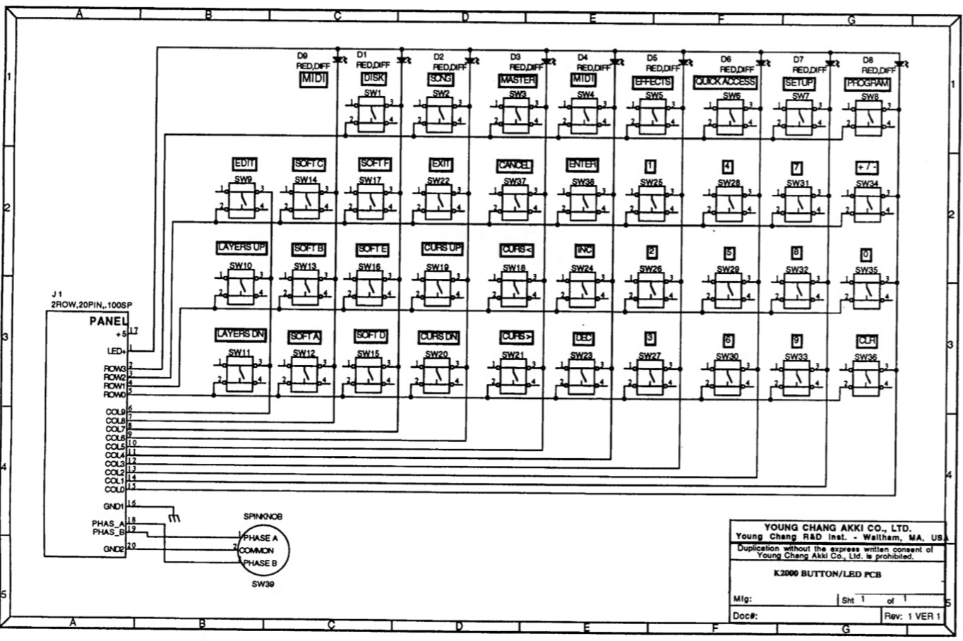
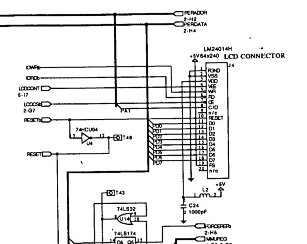
Each component is connect to the main board via a 20 pin ribbon cable. The LCD is a Toshiba T6963 based 240x64 display:

All control and power is delivered over the 20pin ribbon cables.

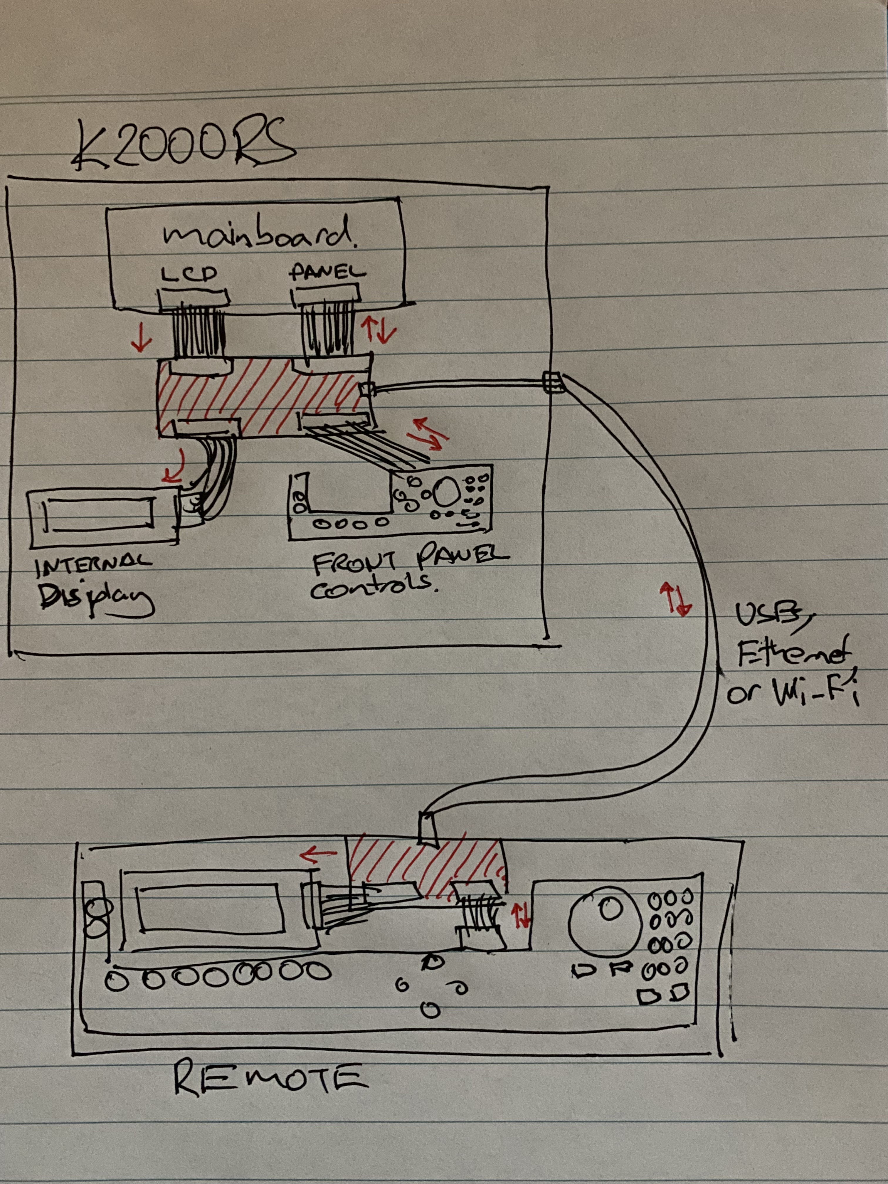
I don’t have an electronics background but have done a bit of coding. The naïve idea I have is to create 2 custom boards (Arduino?) connected via USB, Ethernet or Wireless. One board inside the Kurzweil and the other in the desktop remote enclosure.

The internal board would be inserted internally between the main board and both the display and front panel respectively allowing the signals to pass though directly and also be duplicated and transmitted to the external board so that its display and controls are in sync. For the Desktop Remote I could either buy a keyboard version of the panel board …or create a custom version so I could use my own choice of mechanical switches and encoders etc. I imagine that for the display it would just be relaying the signal one way from the Kurzweil to the desktop remote but the front panel would be 2 way as there are a number of LEDs that change either via direct button presses or software during the synth editing process.

Below is my back-of-the-napkin “design”:

So my question is how feasible is this?

Keyboard version of the panel board:

It’s a big first electronics project, and the stakes are high in the case of a mistake.

I’ll record some random thoughts here. They aren’t complete, but it’s maybe helpful for getting started thinking this through…

Chances are good that something that age is using 5V TTL signaling, which is what the 8 bit Arduinos use. You’d need to work out the purpose of each of the 20 wires in the two (?) ribbon cables. The connector to the display may be sufficiently standard that you can find this out from published documents like application notes for that display; with a 20-pin cable it’s probably a typical parallel connection. (If you can’t find documentation, you’d be ending up buying and learning how to use a logic analyzer.) To remote the display you would either have to “sniff” the data fast enough to not lose any data, or implement a logical interposer where the arduino basically pretends to be the display and then forwards the commands to both displays. I don’t know which would be best but my gut feeling is that I’d look first at the logical interposer as more likely to be reliable.

You might end up needing a high-pin-count Arduino like a the Arduino Mega 2560, which has 70 general-purpose IO (GPIO) pins, at least for the board inside the synth.

USB would be hard because one side has to be host; USB is directional and it’s trickier than you might think. Both WiFi and wired ethernet are hard because you need a whole network stack. All three tend to be easier on more capable 32-bit devices, but those are mostly 3.3V and often not even tolerant of 5V signalling. Easiest would be to use ethernet cable but run CAN BUS over those wires; it’s reliable (it’s used for safety-critical signalling in cars) and takes only two wires, and at short distances can run fast enough for your purposes. This would leave the rest of the ethernet wires for delivering power.

Speaking of power, don’t assume that the power supply in the synthesizer was designed to support the extra load you put on it with two arduinos and an extra display. This is really tricky because you also don’t want to introduce electrical noise into a synthesizer; you might really hear it in the output. I’m presuming that the synthesizer section is reasonably shielded from digital noise from talking to the display and the buttons, but adding another AC/DC power supply inside the case is probably outside their design intent. Also, the Arduino chip introduces noise on the power rail; probably a synth has good power-supply noise rejection but if you tap power from a place they didn’t expect it might reasonably not be filtered. I wouldn’t be at all surprised if you ended up with audio noise as a result of your work. Also, a separate power supply would have to be tied to the same ground as the system so that you have a single voltage reference. So there’s no obviously best option here from my perspective. (I’d probably use a digital oscilloscope and record before and after waveforms of a pure sine wave sample signal to evaluate objectively whether noise was injected.)

I also am a software developer by training, and I have only played with electronics as a hobby. I’ve done successful circuit designs from scratch, including getting circuit boards of my own design made. With that background, if it were my Kurzweil, the electrical noise considerations alone would make me pause to think whether I really wanted to do the project. :relaxed:

I don’t want to be too discouraging, but did want to give some sense of where I’d be starting if I had this in mind for myself.

4 Likes

Hi Michael, thank you for the generous reply.

Not surprisingly there are aspects I didn’t consider but I greatly appreciate your thorough consideration of the problem and possible solutions. Yes, there are 2 ribbon cables. One for the display and one for the front panel controls.

Regarding power, that will definitely be an issue. Apparently they beefed things up a bit for the K2500 series but the K2000 is well known for its barely adequate power supply. They have a 12V connector for an internal SCSI hard drive option but you had to be very careful which one you installed as it may consume too much power and not work. There were lots of reports of that being unreliable even with factory solutions. As for my unit, I replaced the built in floppy for the SCSI2SD card. Both use 5V so that was a direct swap. The original display had a separate connection to power but the new display uses far less and is getting that from the 20pin cable apparently. So there is some power budget but not much and most likely not enough for both internal and external boards, displays etc.

The main issue for me is relaying the display. The K2000 has a very comprehensive midi implementation so key presses and even the display it self if controllable or readable via MIDI System Exclusive messages. In the case of the buttons this is virtually instant but transferring what is on the display is very slow and taxing to the system - sometimes it just fails to update properly at least with the midi remotes I’ve tried. The better ones cache all combinations of possible screens and only pull data when absolutely necessary or when things get out of sync.

Hence my desire for a hardware solution but then I just thought of another option where I could simply mount a video camera in front of the display and send MIDI for the controls. Should work pretty well, but feels like a bit of cheat :wink:

The challenge of the full solution still appeals to me but I’m also conscious of over capitalising and I definitely don’t want to damage the Kurzweil so I’ll do more research and see where it leads. If nothing else I’ll look into CAN Buses and logical interposers as they seem intriguing.

Oh! Full control with MIDI sysex definitely adds multiple approaches here.

There is at least one MIDI library available for arduino. The one that I remember hearing about before is this one that looks quite complete, supports lots of transports, supports all messages including sysex, and has been around for a long time.

If you want the truly classic look for a remote, I suppose you could try to use the old display board you removed if it’s still functional, if you want to learn how to explore what the signals are. That might not be crazy hard, just take some learning. You could hook that up to any 5V arduino with enough GPIOs to read buttons and control display, and also have MIDI for sysex exchange.

You could do the same thing except not try to use a board, just hook up an equivalent display and all the buttons you want to be able to press, and you could use LEDs next to the buttons to display status rather than using the backlit buttons I think I understand are on the synth. You could make the layout be as close as you want to the original, or different if it suits your setup better. And in this case there’s no particular reason to stick with 5V; just choose components that can work with 3.3V and you have lots more options. An ESP32 is cheap has bluetooth and wifi, so I imagine you could use bluetooth or wifi midi adapters instead of worrying about wires to the kurzweil at all!

Both of those options are still substantial work, but feel like the stakes are lower in case of failure; makes it much easier to avoid a mistake “releasing the magic smoke” that keeps your kurzweil humming. :relaxed:

Thinking of another coding approach, you could also get one of those cheap USB MIDI boxes, hook it up to a tablet, and create an application that presents the controls however faithfully to the original you want, and just talks MIDI over USB.

So at least three approaches that don’t involve taking apart the kurzweil, with different challenges and potential fidelity to the original display. All lots of hard work and I’m sure plenty of learning, but all three feel to me potentially achievable with struggle. Using an original display board is hardest because I imagine you’d have to learn some reverse engineering and might require additional tools for that purpose; the other two wouldn’t require reverse engineering at all as far as I can tell.

2 Likes

Just stepping back a bit, I’ve done a bit more reading and I’m slowing realising the enormity of the job to intercept the original signals and transmit those remotely. It would seem the Krz may use some sort of T6963 controller and there’s lots of doco out there for it but not sure how that helps me yet for how I’m trying to use it. I can see others trying to do similar things with other devices and displays where the signals are not known and fail at the point I’m at with trying to decode that… looking like a real rabbit hole!

Anyway, here is another naive question: What issues would I run into if I were to convert (one for one wiring - pin for pin) the 20-pin ribbon cables to another interface (like you would with a breakout board) and then reconstitute them on the remote end for a kind of direct extension? I was thinking something like a DisplayPort connecter and use standard DisplayPort cables, one each for the display and buttons or just the display and handle the buttons via MIDI. This really just to avoid using long ribbon cables that would be hard to manage over a distance beyond a meter or more.

Or something like this:
https://au.rs-online.com/web/p/round-ribbon-cable/6937804
20 or 40 pin. So then it’s just a matter of issues due to length?

BTW the K2000 service manual shows a schematic for the front panel buttons, leds, rotary encoder and the LCD pins:


Actually the schematic says the original dispaly is a Sharp LM24014H:
https://datasheetspdf.com/datasheet/LM24014H.html

The longer the trace, the more you realize that digital signalling is really analog. Those long wires act as capacitors, have inductance, and resistance. And they can pick up electrical noise.

I still think the MIDI sysex route is going to be less work. :smiling_face:

2 Likes

I’m doing the due diligence with deciphering the Kurzweil’s SysEx implementation and have found some pretty good resources as this can reproduce the buttons and reading the display via MIDI. The main issue with this approach is the fact that the Kurzweil is pretty underpowered for processing the volume of messages that may be required while also playing the instrument - which you would want to do while editing and there are inherent delays . All this is pretty instant when you are using the front panel controls directly and it’s that experience I want to reproduce on the remote controller.

Further to the SysEx approach, I’m looking into how I can cache as much information as possible into the remote controller so I can see all that information immediately/locally without having to request it on every button press and then send the changes back to the Kurzweil only when necessary. For example, when I’m scrolling though a list of patches or a range of values for a parameter I only send it once the selection is final - maybe via a type of time delayed buffer so the controller will show an immediate update on its display but wait until I’ve stopped scrolling for an number of milliseconds before sending the last value (or sum there of) to the Kurzweil. I can also pre-populate all the various property values so I can again, not have to request them as they are effectively constants. The SysEx is comprehensive enough to be fairly targeted with querying and updating specific values. I may also do some background data collections to help keep things in sync and pre-load what I may want to select next. For example, when the controller starts up it will request the names of all the patches so the that list can be visible asap and then in the background start fetching individual patches starting with the currently selected one, when not in edit mode, so when I click “edit” it already has full patch values to display. All the editors I’ve seen fetch this stuff on demand so there’s always a half second or more before the display updates. Where I think this may fall down is when I want to adjust values in real time while I’m playing - it may be just too slow or choke in that scenario. That seems to be the consensus from users of other editor/librarian software for the Kurzweil.

See how I go but I’m still thinking the ideal solution would be to be able to intercept the LCD and button signals locally and reproduce them over some sort of fast connection (maybe CAN as you suggested). I have the advantage that the LCD controller is a know entity (parallel RA6963 based, 240 x 64) with some existing Arduino libraries and I have all the pins mapped out courtesy of the K2K service manual. It’s then a matter of being able to reliably sample or relay that data fast enough to send to the remote display.

I’m also intrigued by the concept of having a micro controller act as a type of virtual display. Reading all the values from the ribbon cable and acting as if it is a T6963 so you could then capture the graphical representation of the output digitally then send that to a dumb terminal in the remote for redisplay - as if the K2K had a RGB/HDMI output or similar . When I’ve searched online, the closest I have found of people wanting to something similar is with the goal of capturing the actual text and/or values displayed on the LCD where for me I only want to be able to to retransmit the raw display signals, like-for-like to a remote display of the exact same type. That way I leaving all the processing on the Kurzweil without SysEx clogging the process.

2 Likes

Well it looks like I finally found someone who has trodden this path already and at least has a working prototype. I’m not sure if the project is still going as there are no updates since late 2019 but there is a bit of cool information here:

2 Likes