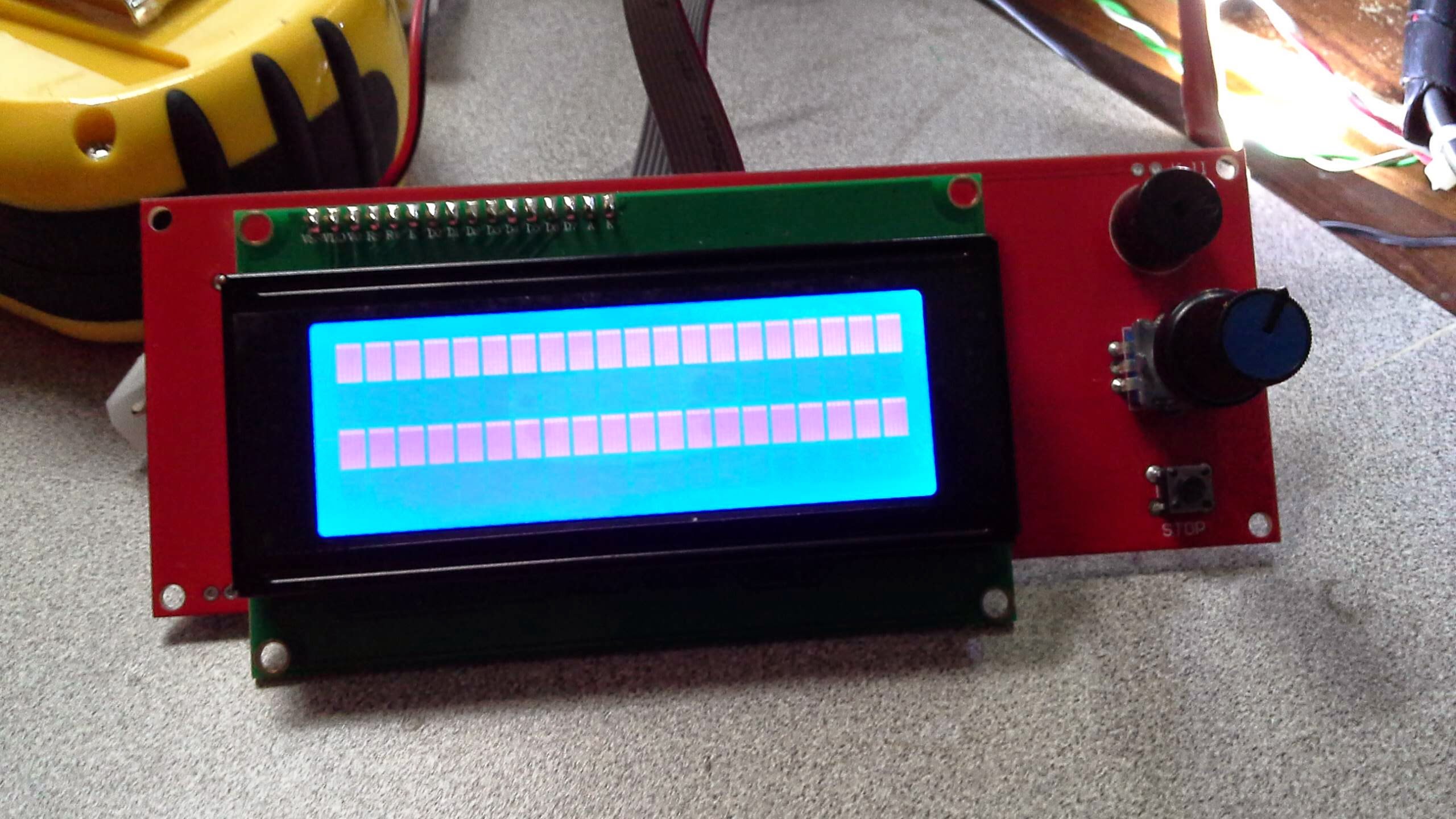
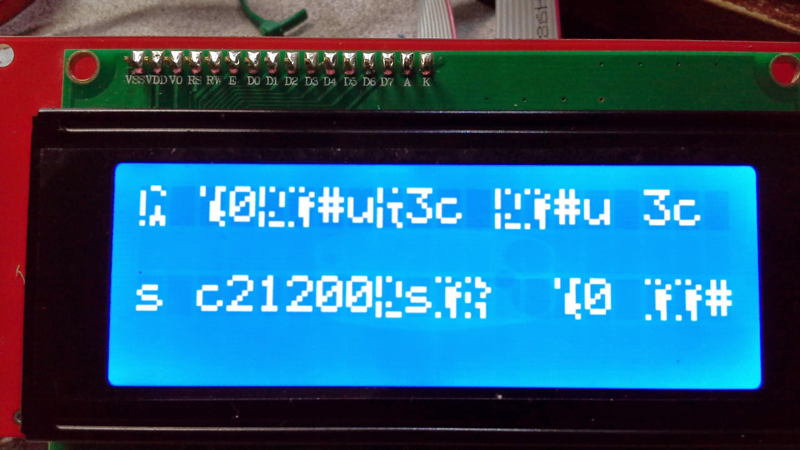
received my lcd from http://robotdigg.com 2 days ago and turned in on firmware and this is all i get.
this is a fresh install of marlin it doesn’t stay solid it blinks. (square lines photo)
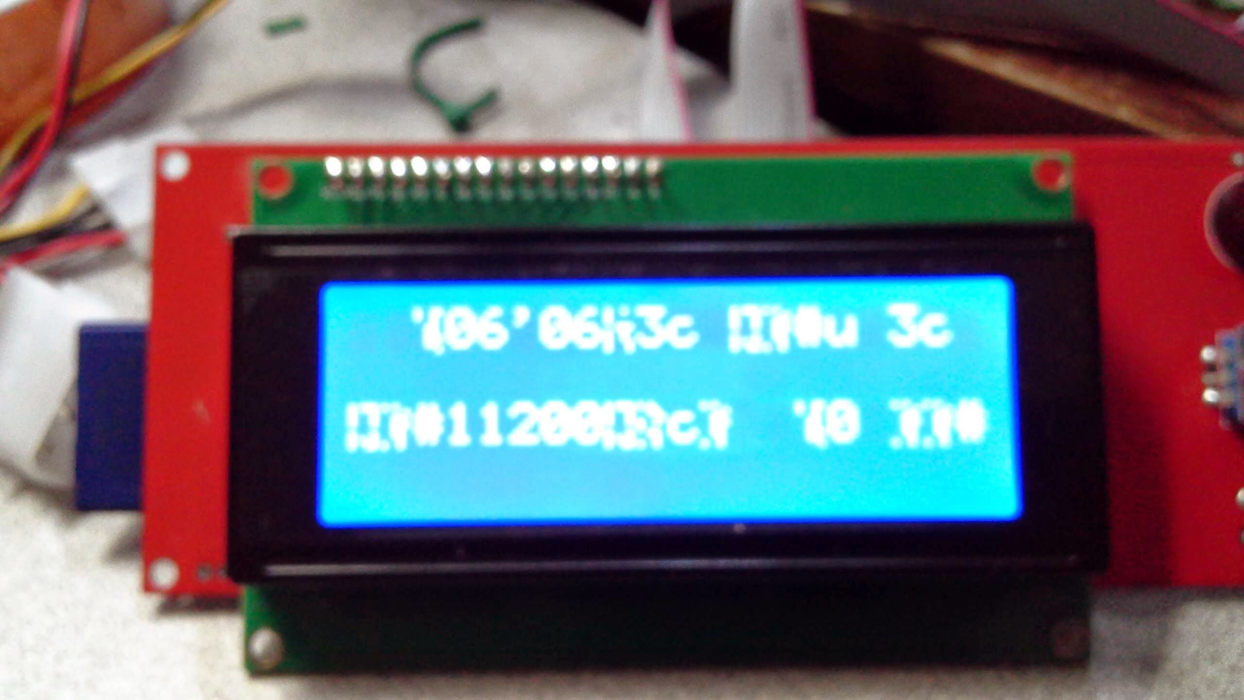
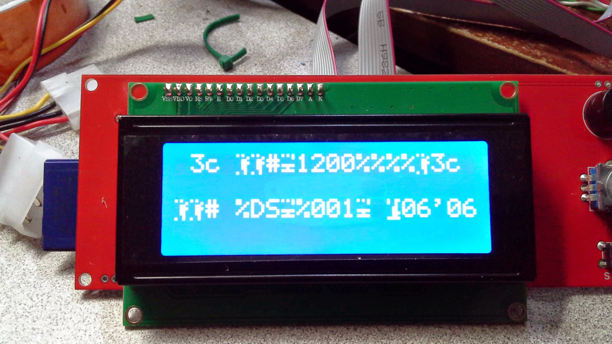
With repetier v91 i get random characters
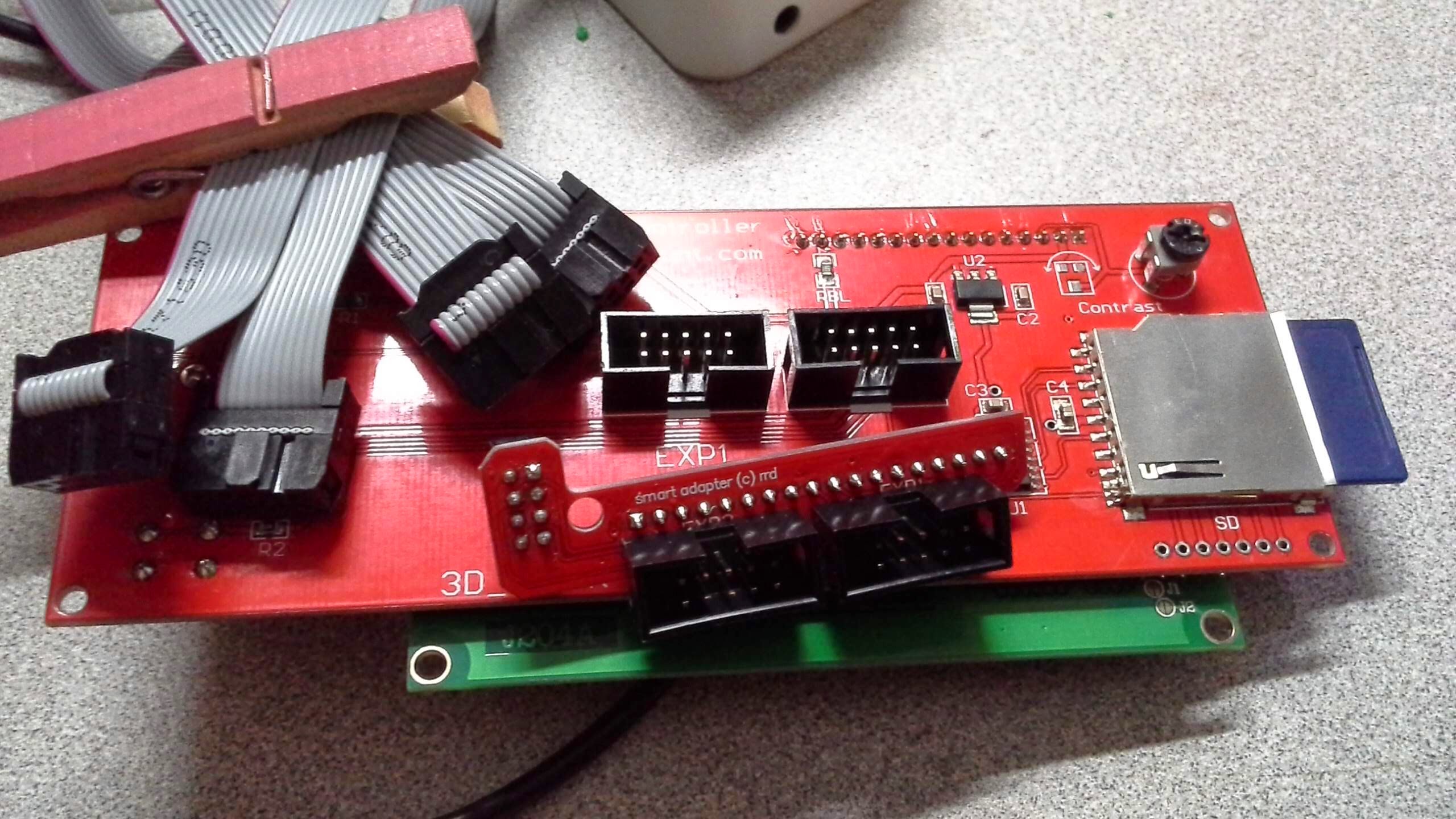
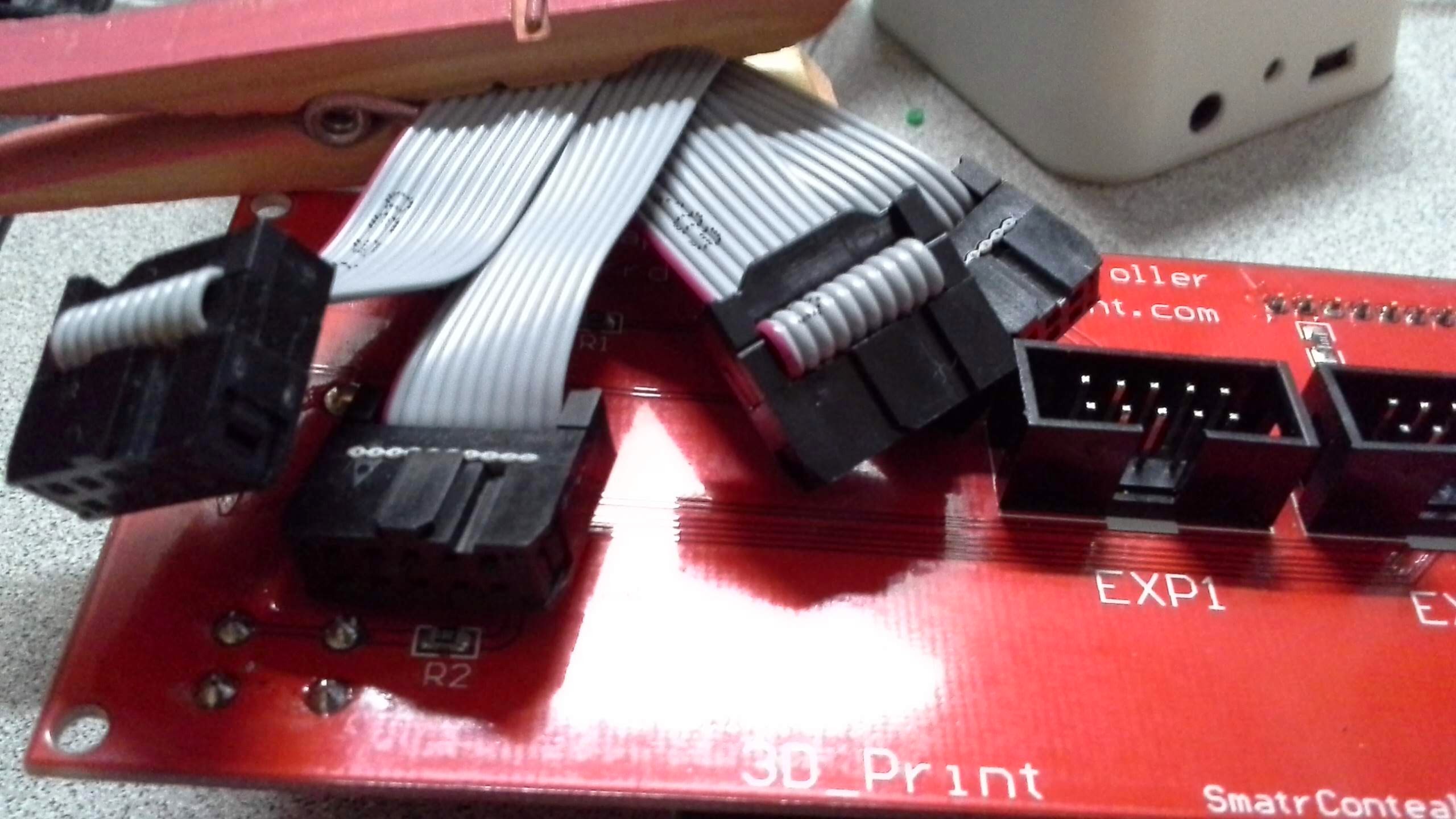
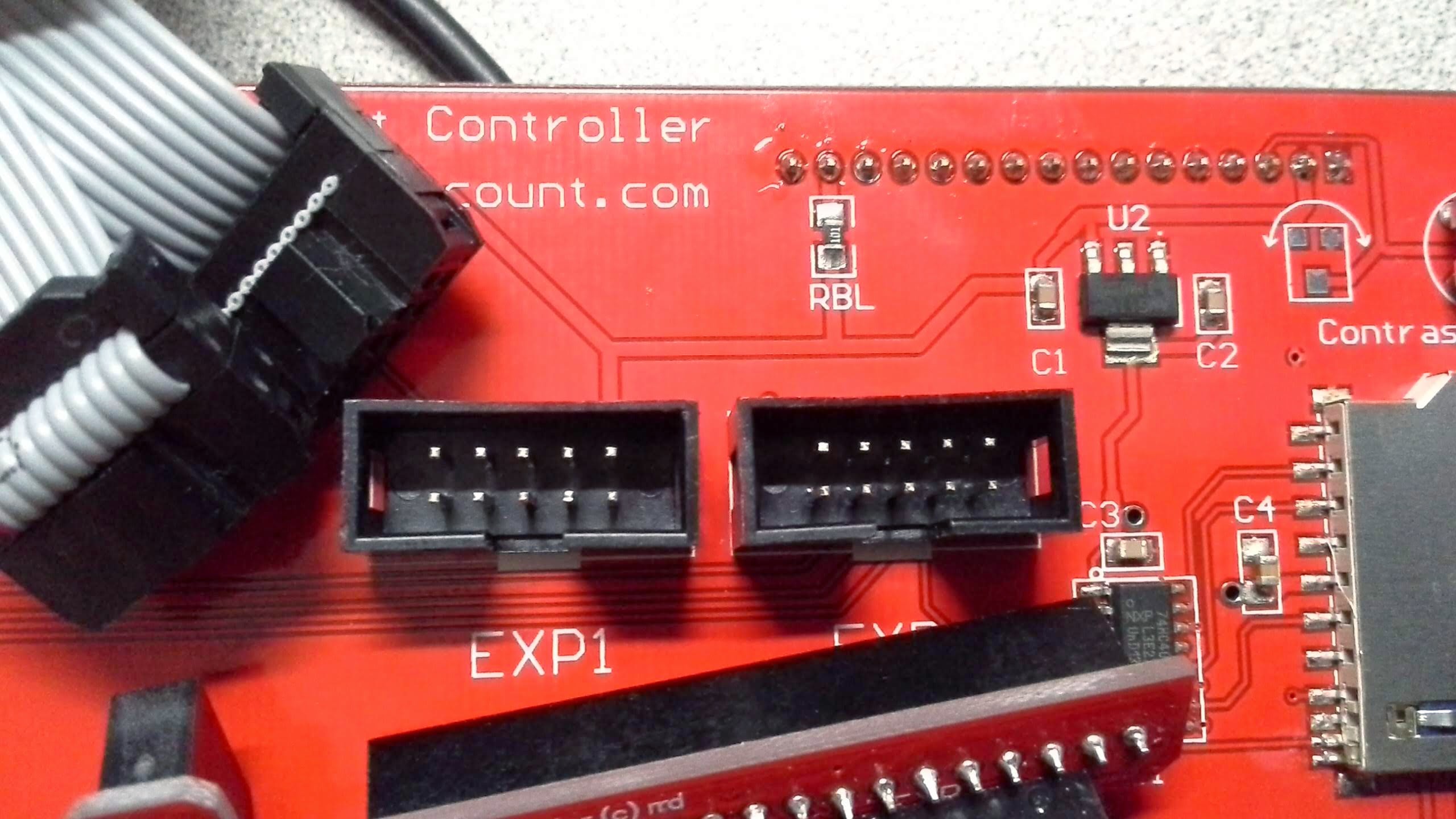
The two cables are notched all four terminals are marked.
I retouched all solder connections on my ramps 1.4 just in case i had bad pin connections
ramps v1.4 atx power supply usb to laptop or desktop (no d1 diode)


Mine did that when I tried running repetier’s firmware on my RUMBA. I don’t run Repetier’s firmware as a result.
well it’s not working with marlin either
I think the end(s) may be reversed on end on one(or both) of your cables find a pinout the confirm tho orientation from the lcd paned ext1 and ext2 to the smart adapter,
wups…
- your contrast may be cranked up too high - in that case whatever is shown on the screen will be blotted by these squares. To fix this try turning down the little adjustment resistor on the back side of the LCD board
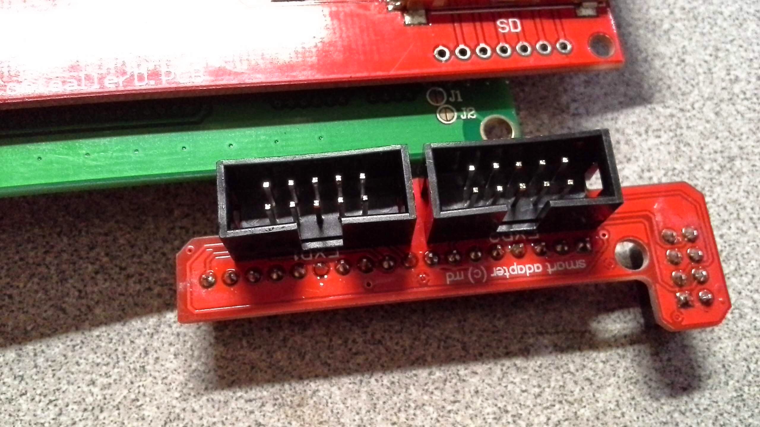
- you may have inserted the connector upside-down, in which case your 5v line recevied 12 v, frying the LCDs electronics. This was my case… You can check it (unless you have already experimented inserting the connectors into the adapter this way and that, in which case it’s definitely toast) with a continuity buzzer of any multimeter - just see which ping end where on the LCD board. If you need it I can dig up the schematics of both LCD board and controller connectors…
But try wiggling that potentiometer first, maybe it’s not that bad…
On the LCD boards i got from China a long time ago the connectors where soldered 180° wrong.
@Christian_Lolkes could be the case, this is why it’s always useful to verify the pinout manually with a buzzer.
with repetier firmware i get random characters which rules out contrast and pinout. I belive it is a hardware issue. but not having another set of ramps 1.4 i cannot eliminate either lcd or electronics
I have had some gruesome experiences with cheap lcd boards, in fact, I never got it to work properly without a lot of work. Every time I want to use a new firmware, it’s an uphill struggle to get it to work. I ended up not using the smrt adapter, and using different pins from the ramps board.And because of the altered pin-configuration, I had to reprogram the firmware. Tricky at best. But start of with using a buzzer, to see how the thing is wired. The schematics are online on several places. Google it. Look for reprap smart display . or go to :
http://reprap.org/wiki/RepRapDiscount_Smart_Controller#Schematics
Good luck, you need it.