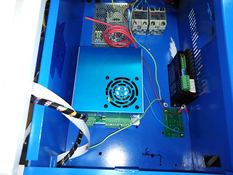
THe placement of components in the rebuilt K40 has bothered me as it makes it difficult to mount the fan except as an external one, and the are where the mains wiring is, is tight.
The placement of the components was largely dictated by the (short) length of the HT wire. As I have new LPS, with a much longer wire, I spent today removing everything and repositioning, lots more holes. One advantage of having broken the laser tube was that I could turn the whole machine upside down without worrying if I would break something  :
:
Just moving the LPS forward 40mm made the difference. I also got two SSR’s mounted (exhaust and air assist)
1 Like
Still going on this rebuild. I’m limited to 1 hour or so a week, so it’s taking a long time. I’ll take some update pictures when I visit makers tonight.
Power is all working, SSR’s work as required. LPS powers up (at least the fan does) can’t test until the new laser tube is in.
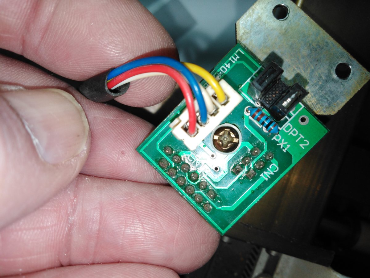
One question regarding the gantry wiring. I have @donkjr circuit diagram of the board but it seems to differ to the way it was wired in this machine (there were jumpers wires from the end of the flat cable to a PCB that managed the endstops)
. The laser did work so I have to assume that wiring was correct but is there an alternative to the one Don has on his site?
1 Like
Sorry, I am not clear on what you mean by;
Perhaps a picture of
…both ends of the jumper wires
…the PCB that manages the endstops
would help.
The board in the picture looks to me like the stock one???
I am not aware of alternate wiring or board for optical sensors.
Thanks @donkjr, I should have shown a photo of the flat cable as well. Jst a confirmation the it’s the same board is enough. I’m replacing the soldered to flat cable so I’ll use the wiring diagram from your website.
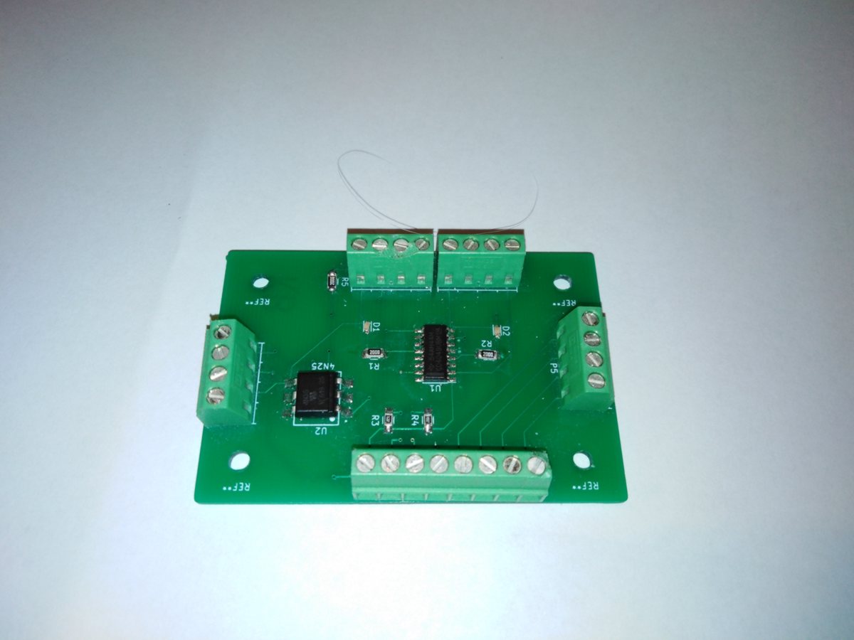
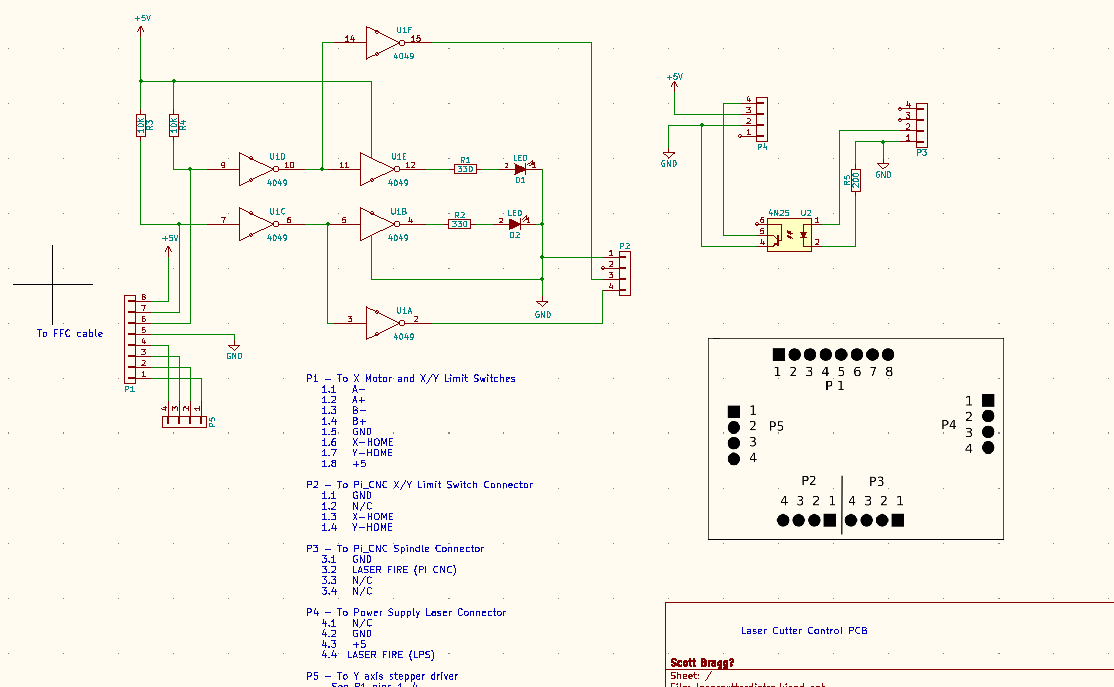
Here is the board that the FFC connects to along with a circuit diagram. It fixes a level issue between the end stops and the Arduino and inverts the laser fire signal.
Do you need anything else from me :)?
@donkjr couldn’t have gotten this far without your online K40 resources.  (and the help from others in this forum)
I’m still considering re-doing that PCB to add an FFC connector or perhaps (as suggested by a friend at Makers), making an adepter PCB with an FFC connector that solders in place of the screw terminals currently used. - this may be the quicker solution.
I have wired up this PCB with the gantry PCB on the bench and tested that the wiring is correct and wrking.
Laserweb and grbl have been updated/configured so getting close to having movement again in the K40. Pump and water reservoir are being done, flow switch and temperature sensor to be added.
2 Likes
Did you know about this adapter from Awesome Tech:
https://awesome.tech/k40-middlemen-board/
not sure if it helps but I was on the site yesterday and thought of your project.
2 Likes
I have not seen that one. Looks like it would solve the problem.
I might still look at a small adapter/breakout board as the cost would be about the same as the middleman board with delivery, exchange rate, etc. Delvery time would be about the same. Depends on me getting stuck into the design or taking advantage of a rare, rain free, warm day outside!
1 Like
If you still need one, I’ve just taken mine out of my machine, cover postage and it’s yours
1 Like