Instructions on how to splice the HV cable safely are in @donkjr 's blog, linked from this Getting Started with CO2 Lasers article:
Here’s a search for more discussion on this forum:
https://forum.makerforums.info/search?q=hv%20splice
Instructions on how to splice the HV cable safely are in @donkjr 's blog, linked from this Getting Started with CO2 Lasers article:
Here’s a search for more discussion on this forum:
https://forum.makerforums.info/search?q=hv%20splice
I’ve been over the stuff in @donkjr’s blog and looked at all the videos he’s linked on the subject of tube change. Splicing the wire is not a problem but my main concern was the best/correct way to attach the wire to the anode. The Cloudray tube does come with a wire attached (not sure on the method - mechanical or soldered) so all I should need to do is to choose the best location for the splice.
Is it 7 or 8 mm that fits on a “standard” k40 laser tube?
Regards Bernd
CLoudray told me 7mm was fine. Hope they’re right.
Thanks for the response 
Sorry for the delay in responding:
I would place the HV connector where the point of splice needs to be. Essentially the connector is in place of the spice. I like to attach 1/2 a high voltage connector to the HVT’s wire and then the other side of the connector to the anode wire. That way when I replace either the tube or the HVT I just remove and replace 1/2 the HV connector, no splices.
In the case where you have a preassembled HV connector & wire a splice will be necessary. RTV will work, make sure it is the high dielectric type. https://amzn.to/3myJarN
Use “ball soldering” on any solder joints to prevent corona. Keep in mind that the voltage can jump 1-2" if uninsulated. It also can find uninsulated tracks through gaps in connectors to ground.
The anode pin is made of hardened metal (Inconel?). You actually cannot solder to it. If you try you can crack the tube. Those that do actually create a cold joint that mechanically attaches the wire to the pin, no better than twisting it on. Unlike normal circuits 20,000v does not need a gas tight connection. Wrapping the wire on the pin before potting it in silicon is sufficient. Wrapping followed by a tube filled with silicon is the traditional method.
Not much I’ve been able to do on the K40 this week as I’m waiting for parts. Most of the AC wiring has been done with the exception of the two SSR’s that will control air assist and exhaust fans.
I’ve been spending my spare time creating wiring diagrams, largely based on those provided by @donkjr . I’m trying to document all the wiring colours used previously with the new stuff I’m putting in - just in case I get hit by a bus and someone else has to pick up the job. 
I’ve been using kicad for this. No PCB’s needed so just using the schematic editor.
I’ve also been working on a new control panel layout - first draft. Not sure if there is going to be a Z axis platform but ‘just in case’ . The ‘display’ will be a 3.2" il9341 based, touch screen unit probably driven by either an Arduino nano or perhaps an ESP32.

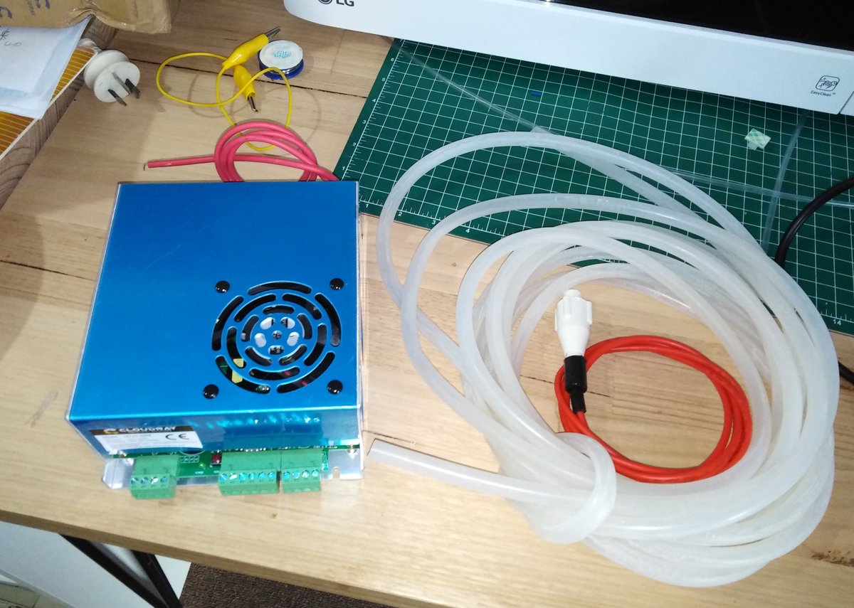
Parts are slowly starting to trickle in. Today I got the new power supply and some silicone tubing. These are from Cloudray so my new laser tube can’t be far away
[Most of the stuff I’ve been getting from China arrives via a company called UCL and is forwarded on by Australia Post. Works well but the tracking number I get from Aliexpress is different from the AusPost one so I have no idea what I’m getting. Like Christmas every day!]
EDIT: laser tube and HT connector (thanks @donkjr for suggesting this) arrived today.
why not use a mks mk 3 board costs 29 euros and your done? uses grbl-lpc off github
The controller is about the only thing that is NOT being replaced! Currently running Laserweb on a Raspberry Pi and a [Protoneer CNC hat. This has ben working very well.
ok misunderstood. Im rebuilding mine at the moment in to a metre by 1.2 metre cage, it will be an open style laser with protection where needed, Already just done one at 800 x 670 cutting area, this will be at least 900 /1m cutting area plus a built in rotary underneath and 10 watt diode on top.shelf.
Early stages, built the external frame now sorting out the internal frame and tube. Plastic pipe is an representative tube. Useful to get the frame just right… Everything will run on flat superfast/smooth linear rails, cost a small bomb but worth every penny.
Thats the idea anyway! Probably take the tube up to a 50 or 60 when the original 40 dies.
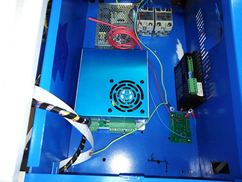
THe placement of components in the rebuilt K40 has bothered me as it makes it difficult to mount the fan except as an external one, and the are where the mains wiring is, is tight.
The placement of the components was largely dictated by the (short) length of the HT wire. As I have new LPS, with a much longer wire, I spent today removing everything and repositioning, lots more holes. One advantage of having broken the laser tube was that I could turn the whole machine upside down without worrying if I would break something  :
:
Just moving the LPS forward 40mm made the difference. I also got two SSR’s mounted (exhaust and air assist)
Still going on this rebuild. I’m limited to 1 hour or so a week, so it’s taking a long time. I’ll take some update pictures when I visit makers tonight.
Power is all working, SSR’s work as required. LPS powers up (at least the fan does) can’t test until the new laser tube is in.
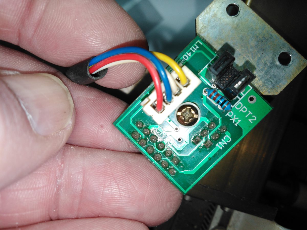
One question regarding the gantry wiring. I have @donkjr circuit diagram of the board but it seems to differ to the way it was wired in this machine (there were jumpers wires from the end of the flat cable to a PCB that managed the endstops)
. The laser did work so I have to assume that wiring was correct but is there an alternative to the one Don has on his site?
Sorry, I am not clear on what you mean by;
Perhaps a picture of
…both ends of the jumper wires
…the PCB that manages the endstops
would help.
The board in the picture looks to me like the stock one???
I am not aware of alternate wiring or board for optical sensors.
Thanks @donkjr, I should have shown a photo of the flat cable as well. Jst a confirmation the it’s the same board is enough. I’m replacing the soldered to flat cable so I’ll use the wiring diagram from your website.
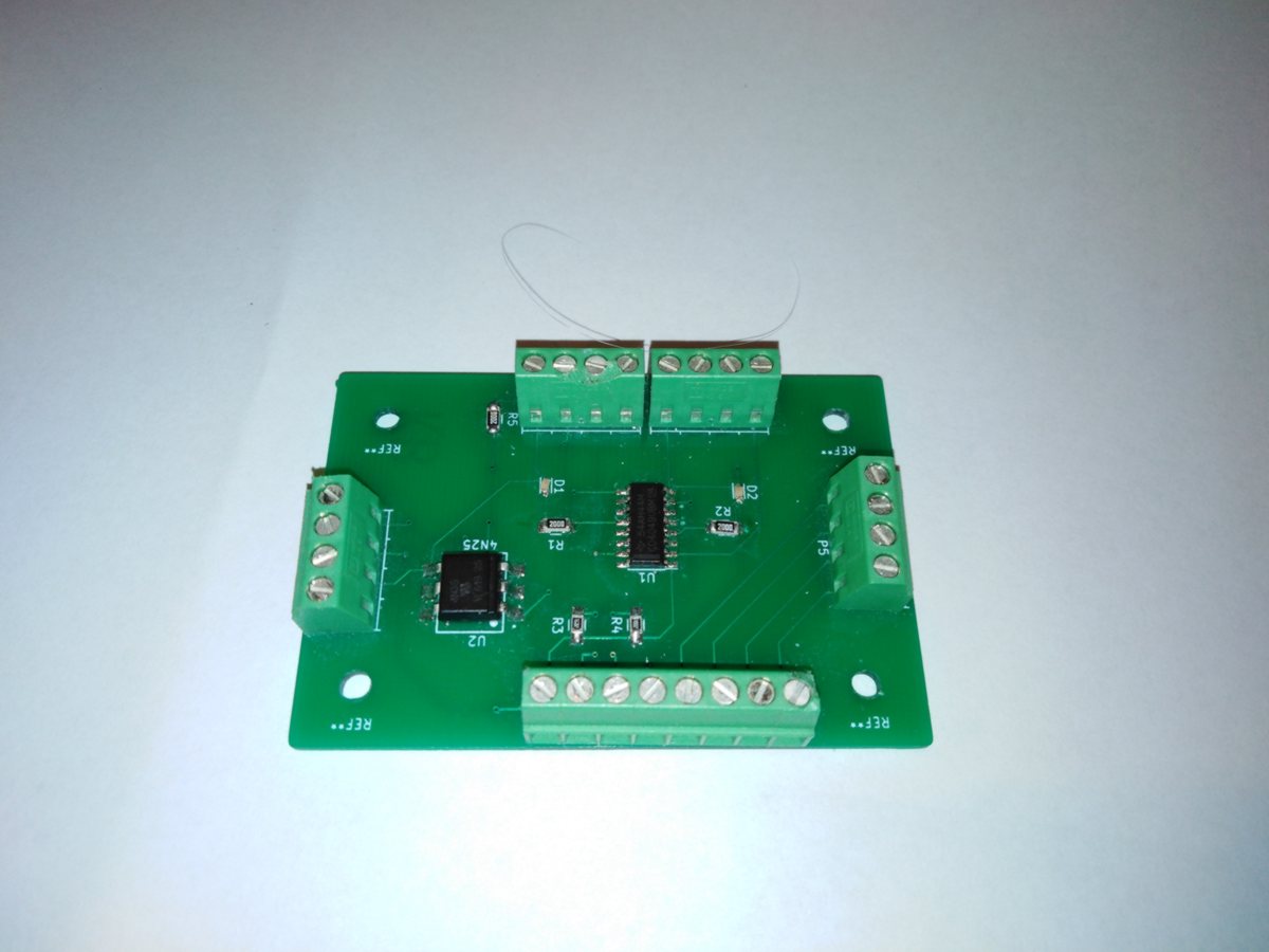
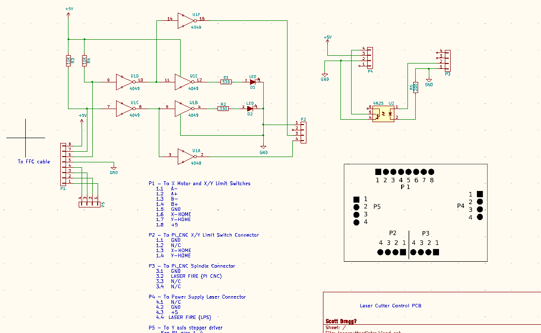
Here is the board that the FFC connects to along with a circuit diagram. It fixes a level issue between the end stops and the Arduino and inverts the laser fire signal.
Do you need anything else from me :)?
@donkjr couldn’t have gotten this far without your online K40 resources.  (and the help from others in this forum)
I’m still considering re-doing that PCB to add an FFC connector or perhaps (as suggested by a friend at Makers), making an adepter PCB with an FFC connector that solders in place of the screw terminals currently used. - this may be the quicker solution.
I have wired up this PCB with the gantry PCB on the bench and tested that the wiring is correct and wrking.
Laserweb and grbl have been updated/configured so getting close to having movement again in the K40. Pump and water reservoir are being done, flow switch and temperature sensor to be added.
Did you know about this adapter from Awesome Tech:
https://awesome.tech/k40-middlemen-board/
not sure if it helps but I was on the site yesterday and thought of your project.
I have not seen that one. Looks like it would solve the problem.
I might still look at a small adapter/breakout board as the cost would be about the same as the middleman board with delivery, exchange rate, etc. Delvery time would be about the same. Depends on me getting stuck into the design or taking advantage of a rare, rain free, warm day outside!
If you still need one, I’ve just taken mine out of my machine, cover postage and it’s yours