Hello,
Where I can to connect the pwm wire of my laser with grbl-hal and skr 1.3?
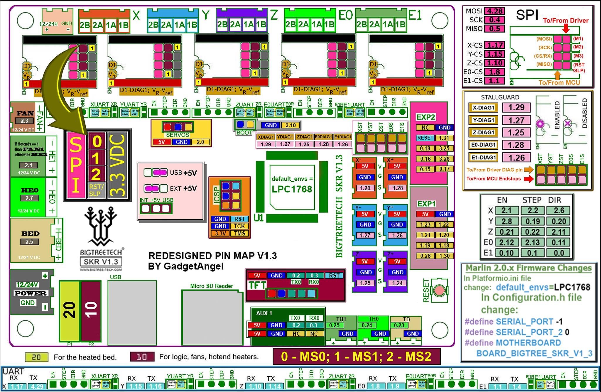
It’s ok in positive of the H-BED 2.5 ?
The +12V and GND of my laser are connected to the machine power supply, 12V 40A output.
Best regards
Hello,
Where I can to connect the pwm wire of my laser with grbl-hal and skr 1.3?
It’s ok in positive of the H-BED 2.5 ?
The +12V and GND of my laser are connected to the machine power supply, 12V 40A output.
Best regards
It depends on what your laser cutter power supply wants for PWM control. Some LPSs want to see the PWM signal pulling low( active Low ) and some what to see the PWM signal pulling high( active High ).
My K40 LPS likes active Low so I use the negative side of the HBed. Besides, isn’t the positive side of the HBed tied to your input voltage(12V or 24V) therefore it is not even controllable?
PWM/TTL input: DC3.3V-12V
Did I miss what kind of machine you are trying to control?
It wasn’t mentioned yet @donkjr but I now realize that the above statement probably relates to a diode laser module. I was thinking CO2 and couldn’t make sense of that line but now it makes sense.
I would use one of the open-drain MOSFET drivers that support PWM.
Looks like you will need a pullup to 12V.
Schematic here: BIGTREETECH-SKR-V1.3/SKR-V1.3-SCH.pdf at master · bigtreetech/BIGTREETECH-SKR-V1.3 · GitHub
Cartesian build by me, with 5,5W output laser, NUBM0A 455nm with grbl-hal
Works in +HB but is always ON.
I have tried with M3, M4, M5 codes and always is ON
$32
$32=1
ok
M3
ok
b’$G\n’
[GC:G0 G54 G17 G21 G90 G94 G49 G98 G50 M3 M9 T0 F0 S0.]
ok
M4
ok
M5
ok
This sets the spindle speed for the maximum 5V PWM pin output. Higher programmed spindle RPMs are accepted by Grbl but the PWM output will not exceed the max 5V. By default, Grbl linearly relates the max-min RPMs to 5V-0.02V PWM pin output in 255 increments. When the PWM pin reads 0V, this indicates spindle disabled. Note that there are additional configuration options are available in config.h to tweak how this operates.
This sets the spindle speed for the minimum 0.02V PWM pin output (0V is disabled). Lower RPM values are accepted by Grbl but the PWM output will not go below 0.02V, except when RPM is zero. If zero, the spindle is disabled and PWM output is 0V.
S spindle speed command. This is the default operation of a milling machine to allow a pause to let the spindle change speeds.G1, G2, or G3 motion commands when programmed with a S spindle speed (laser power). The spindle PWM pin will be updated instantaneously through each motion without stopping. Please read the Grbl laser documentation and your laser device documentation prior to using this mode. Lasers are very dangerous. They can instantly damage your vision permanantly and cause fires. Grbl does not assume any responsibility for any issues the firmware may cause, as defined by its GPL license.G7, G8, G96 and G97 commands. If the HAL driver supports spindle sync G33 and G76 are also enabled. Lathes, like lasers, are very dangerous. Grbl does not assume any responsibility for any issues the firmware may cause, as defined by its GPL license.Spindle PWM frequency in Hz
Either, $34 or $33 works to me.
IIRC diode laser modules( that is what you have ) have a 12V, Sig(5V level), Gnd 3-pin configuration with the Signal being ACTIVE HIGH. What that means is if the Sig pin is at 5V then the laser is ON and if the Sig pin is low(0V) then the laser is off.
You should be able to put a volt meter across the Sig and Gnd pins and see this.
You don’t want 12V on the signal pin if it’s a 5V control.
If you see 5V and the laser is off then pull Sig to 0V/Gnd and the laser goes on then it’s called ACTIVE LOW.
Figure out what you have and let us know.
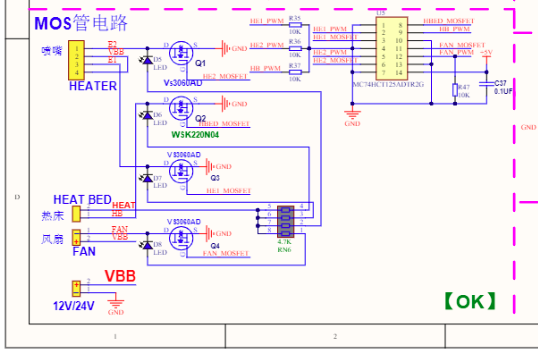
HB mosfet output are 12/24V not 5V.
My laser works with pwm from 3V3 to 12V.
You can go OFF with 0V and ON with 3V3, 5V, 12V but also I need to control de power 0~255. With $33, I guess.
Spindle PWM frequency in Hz
What do you mean by HB output? It would help me to understand if you would refer to the schematic.
I’m confused? The MOSFETs are open-drain so the output is not any particular voltage until you pull them up. You can pull up the output to whatever voltage your PWM voltage requires??
Heat Bed output
I am going now to make a test file ir order to try this matter.

I think you are confusing the repeating PWM frequency with the PWM pulse width.
Pulse Wide Modulation very seldom is a single pulse of X time on and the rest off. It is usually a repeating pulse and that is what $33 specifies. 1/freq gives you the period of the repeating pulses.
Setting the pulse width which is repeating is what is done with the M3/M4 commands as in M3 S100, M3 S255, etc. The M3,4,5 commands are Spindle commands because of it’s CNC heritage.
http://linuxcnc.org/docs/html/gcode/m-code.html#mcode:m3-m4-m5
Yes, by default the freq is 1khz
By default, the spindle PWM frequency is 1kHz, which is the recommended PWM frequency for most current Grbl-compatible lasers system. If a different frequency is required, this may be altered by editing the
cpu_map.hfile.
In spindle mode, the M3 is CW and M4 CCW but in laser mode is diferente $32=1
The laser is enabled with the M3 spindle CW and M4 spindle CCW commands. These enable two different laser modes that are advantageous for different reasons each.
M3 Constant Laser Power Mode:
M3 constant power mode, it’s a good idea to add lead-in and lead-out motions around the line you want to cut to give some space for the machine to accelerate and decelerate.M3 can be used to keep the laser on for focusing.M4 Dynamic Laser Power Mode:
M4 dynamic mode turns off the laser. It only turns on when the machine moves. This generally makes the laser safer to operate, because, unlike M3, it will never burn a hole through your table, if you stop and forget to turn M3 off in time.I unplug all cables from my skr. And there is a green led that lights up every time the M3, M4, M5 code is sent. It is 2.5 pint. it is not the pisitive pin, it is the nevative.
Run a test with svg file and it works, now I can see it turning on and off. Look better now, tomorrow I will do more tests. Thank you very much.
as was mentioned and if you look at the schematic the FET(transistor/switch) for the HeatBed is connecting Ground to the Neg side of the connector. The Positive side of the connector is wired directly to the boards input power( 12v or 24V ).
Think of it like this: You have a battery with Neg side and Pos side and you have a light(or heater element as in the heat bed) with 2 wires and it really doesn’t matter which wire since the light and the heater will heat no matter which way it is connected. Now you connect one wire to the Pos side of the battery. YOU will be like the FET/transistor/switch when you take the other wire from the light/heater and touch it on/off to the Negative side of the battery. For PWM you hold it on for 5 seconds then off for 5 seconds, on for 5, off for 5. you just did 50% duty cycle PWM.
This is how those things work on your board. The negative side is getting connected and disconnected to Ground which is the negative side of your input power supply.
Yes, hardware pwm pin is connected to the MC74HCT125ADTR2G marked U5 in skr 1.3 board, but I have not found a direct pin header for HB-PWM 2.5 pin 68 in LPC1768 P2.5/PWM1.6/DTR1/TRACEDATA0
I guess that I could use the 2.0 pin, is direct from servo header. In LPC1768 is P2.0/PWM1.1/TXD1
SKR-V1.3-SCH.pdf (113.4 KB)
In btt_skr_1.3_map.h file say:
btt_skr_1.3_map.h - driver code for LPC176x processor, pin mappings compatible with BTT SKR v1.3 board
Part of grblHAL
#ifdef SPINDLE_PWM_PIN_2_4
#define SPINDLE_PWM_CHANNEL         PWM1_CH5    // MOSFET3 (P2.4)
#else
#define SPINDLE_PWM_CHANNEL     PWM1_CH6    // BED MOSFET (P2.5)
#endif
#define SPINDLE_PWM_USE_PRIMARY_PIN   false
#define SPINDLE_PWM_USE_SECONDARY_PIN true
in grbl-lpc/pwm_driver.c I found this:
const PWM_Channel_Config PWM1_CH1 = {
    &(LPC_PWM1->MR1),   //Match Register
    (1 << 9),           //PWM Enable
    (1 << 1),           //Latch Enable Register
    (0x2 << 4),         //PINSEL3 - P1.18
    (0x1 << 0)          //PINSEL4 - P2.0
};

const PWM_Channel_Config PWM1_CH2 = {
    &(LPC_PWM1->MR2),   //Match Register
    (1 << 10),          //PWM Enable
    (1 << 2),           //Latch Enable Register
    (0x2 << 8),         //PINSEL3 - P1.20
    (0x1 << 2)          //PINSEL4 - P2.1
};

const PWM_Channel_Config PWM1_CH3 = {
    &(LPC_PWM1->MR3),   //Match Register
    (1 << 11),          //PWM Enable
    (1 << 3),           //Latch Enable Register
    (0x2 << 10),        //PINSEL3 - P1.21
    (0x1 << 4)          //PINSEL4 - P2.2
};

const PWM_Channel_Config PWM1_CH4 = {
    &(LPC_PWM1->MR4),   //Match Register
    (1 << 12),          //PWM Enable
    (1 << 4),           //Latch Enable Register
    (0x2 << 14),        //PINSEL3 - P1.23
    (0x1 << 6)          //PINSEL4 - P2.3
};

const PWM_Channel_Config PWM1_CH5 = {
    &(LPC_PWM1->MR5),   //Match Register
    (1 << 13),          //PWM Enable
    (1 << 5),           //Latch Enable Register
    (0x2 << 16),        //PINSEL3 - P1.24
    (0x1 << 8)          //PINSEL4 - P2.4
};

const PWM_Channel_Config PWM1_CH6 = {
    &(LPC_PWM1->MR6),   //Match Register
    (1 << 14),          //PWM Enable
    (1 << 6),           //Latch Enable Register
    (0x2 << 20),        //PINSEL3 - P1.26
    (0x1 << 10)         //PINSEL4 - P2.5
};
Is ok to changing
#ifdef SPINDLE_PWM_PIN_2_4
#define SPINDLE_PWM_CHANNEL         PWM1_CH5    // MOSFET3 (P2.4)
#else
#define SPINDLE_PWM_CHANNEL     PWM1_CH6    // BED MOSFET (P2.5)
#endif
by this in btt_skr_1.3_map.h file?
/**#ifdef SPINDLE_PWM_PIN_2_4
#define SPINDLE_PWM_CHANNEL         PWM1_CH5    // MOSFET3 (P2.4)
#else
*/
#define SPINDLE_PWM_CHANNEL     PWM1_CH1    // BED MOSFET (P2.0)
/**#endif*/
So works fine
#ifdef SPINDLE_PWM_PIN_2_4
#define SPINDLE_PWM_CHANNEL         PWM1_CH5    // MOSFET3 (P2.4)
#else

#define SPINDLE_PWM_CHANNEL     PWM1_CH1    // SERVO (P2.0)
#endif
And the pwm pin of the laser connected in servo pin 2.0, works perfect.
Thanks for all.
Best regards