Making a very square Y stage is not as easy as the manual would suggest. One can manage to make it skewed and it is almost impossible to make it square after you’ve tightened it very well. Believe me I tried to press on the corners very hard but gave up fearing I’ll brake the legs. So I loosened again all nuts and put a folded paper shim in the ZPlate’s notches/slots and forced the YRods in there flush with the nuts. Then switched repeatedly between measuring squareness and measuring distances.
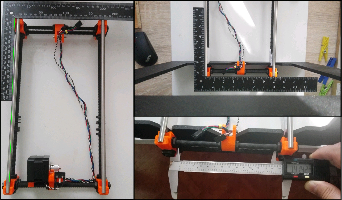
Now in the Prusa dimensions sketch (https://is.gd/T9ccHz) it mentions 152mm between the plastic legs, which I found very unreliable to measure because of the printing part so I decided to measure between the nuts (I measured the washer and the nut many times, made an average and settled on 5.43mm for each pair, 10.86 total which results in an 141.14mm in between the nuts when substracted from the 152mm required value). I have now about 141.5 for each short YRod. I can measure many values for the in-between-plastic-legs, including the 152mm, but they vary wildly depending where I settle my caliper jaws.
But the frame should be pretty square now.
PS: I believe I should have put on the bed carriage too and play it along the smooth rods to check if it goes smoothly but I guess the bearings and also the slots they sit in will take the deviation. Might re-do it though
Yeah, I did put the carriage on the smooth rods and man what a smooth slide there is … it was way tougher before which makes me think I had this axis skewed from the beginning. I am relieved at least for this part
Curious if you checked your L-square for squareness? I have a couple “office supply store” quality squares that are actually 0.5-2 degrees out of square when I check them against a machinist’s square.
Prusa built the printer without any square so I should be able to use it
To answer your question no and I don’t have a proper way to test it but the usual line on paper test (https://is.gd/0ZXMJj)
Ok, I could actually measure the diagonals using my 150mm caliper. Dunno why it wasn’t obvious to me from the beginning but using the caliper’s tail actually goes way past 150mm and I only needed the difference between the two diagonals, not absolute lengths.
It looks like the difference is about 0.5-0.6mm. Is this a too large difference? That is 0.152% deviation (if I calculated it right).
Honestly it shouldn’t matter how square the y axis is. What matters most is the difference between the rods.
All that matters is that each axis rods are parallel to each other, and the each axis is perpendicular. Unfortunately with this design there aren’t any diagonal braces, which means a few things: the y-z connection can twist and flex, the y axis can also twist and flex, and the printer must be placed on a flat surface. The only good axis is the z, and even then the motors can get out of sync. The x axis is non-adjustable which can be good or bad.
The twisting of the y axis will be your biggest problem.
@Stephanie_A What do you mean by “The twisting of the y axis” ? Are you talking about this step in the instructions manual: https://is.gd/dD5JYx ?
Y carriage can be un-square in the Y plane (issue resolved if diagonals are the same length) or can be un-level in the Z plane, that is when each end of each smoth rod is at a different height in Z plane.
Prusa instructions say to twist the Y gantry until all four legs are sitting firmly on the ground without rocking even the slightest. That indeed is very difficult to achieve, especially after you stick the felt-thing pads .
With that in mind there are three directions tha bed can be off in relation to ZPlate namely rotation around Y axis (left side is higher/lower than right side), rotation around X axis (front of bed is higher/lower than the back) and rotation around Z axis (one can easiest see it when the X Rods aren’t parallel with the lines on the bed).
The first one can really be tackled easy by having the ZPlate rotated accordingly (ex: one YRod is fully butted in the ZPlate’s slot while the other is higher), the last one can be solved by having the ZPlate at slightly different distances from the back feet (they say 100mm but I ended up at 99.45 and 100.1, others even have larger difference) BUT the rotation around X axis is the one that I believe is the most difficult to adjust/work-around because the ZPlate is presumably perpendicular to the YRods by the nature of the fastening itself (nuts and washers) so if the front of the bed is higher/lower than the back then it needs to be tackled at the source of the misalignment.
That’s what I mean, if there was a brace from the top of the z plate to the back of the y assembly it could be used to adjust both the twist of the y axis and keep it perpendicular to the z axis. I bet it’s quite easy to take the y assembly and twist it so that one rod is higher in the front than in the back. Keeping it flat requires it to be on a flat surface and the feet to be shimmed.
@Stephanie_A On the plus side, the Y bed only really needs to be square to the ZX gantry right below the X bridge / nozzle, so some B-axis twist (eg one Y rod higher at one end) isn’t necessarily going to impact quality.
@Stephanie_A There are many incarnations of the Prusa MK2 Z-Brace (https://is.gd/R1SLlA) out there that put some more rods to bridge Y and Z but I am yet to find one that doesn’t reduce the print volume and is adjustable and doesn’t necessitate to take the printer apart … well tbh I didn’t do much research on that.
About the feet… they can be whatever as long as the YXZ are square, so the printer can even be croooked to one side, it’s all relative between the 3 axes.
@Ryan_Carlyle I don’t really follow you :-/ … front will get right under the X gantry at certain movements so front bed has to be square with ZX at some point, also every other point on the bed, resulting in a need for the whole bed to be level with ZX.
@Florian_Ford Good point, I was wrong, the Y bed linear hardware is done the dumb way on this design. (In comparison, putting the “carriage” on the stationary frame and supported rods/rails on the bed makes Mendels waaaay stiffer and more resistant to alignment error.
we have to work with what we have … there aremany things that could be improved quite easily by design… too many to mention but thousands swear by its quality prints so let’s see … after hardware proficiency the kit builder has to become proficient in calibration by software, menus, gcodes, probing points, etc etc
I hate these empirical results vs good engineering. I have gone through so many printers that people claim are great, only to find countless engineering flaws. Flaws that would either cost nothing to fix, or a few pennies at mass quantities. It typically boils down to “it works, mostly”. However what it leads to are the issues you are experiencing. I don’t know if it’s because the designers don’t care, or don’t know about it, or think that it’s good enough. Either way, it shows a lack of effort.
I think it’s important to consider the different schools of thought in printer design here:
Quality by design and parts fabrication – the printer self-aligns square when assembled
Quality in assembly precision – whether by end-users with L-squares or OEM jigs
Software compensation – probing auto-corrects for assembly errors
What’s really interesting to me is how Prusa has evolved in his designs in this area. The Prusa Mendel i2 was classic RepRap strategy #2 for assembly precision. The i3 adopted the lasercut sheet approach and picked up a healthy dose of relying on parts fab precision (at least for the ZX gantry). Then the i3 mk2 picked up a lot of auto-calibration functionality.
Yes but that quality can lack repeatability and robustness. Something I found almost immediately with my p3steel was that the frame twists if the surface it was on was not flat. Also ringing from an unbraced frame and belts. Sure it was accurate, but i couldn’t print anything fast because of the ringing.
#1 is very expensive if you apply it to the whole machine. #2 is difficult for the user. #3 works but has limitations.
In a good machine, things that need to be adjustable are such, and things that don’t need to be adjustable are made to a tolerance that the other parts can be adjusted to compensate. This lowers the cost, while removing the extreme difficulties of #1. For example look at the lulzbot taz6. Each axis is independently assembled, while some portions are 3d printed, others are machined. You can adjust where needed because of enough tolerance in the machining. The frame itself is rigid and resists twisting.